
Integral 3D graphene-carbon hybrid foam and devices containing same

a graphene-carbon hybrid foam and integrated technology, applied in the field of carbon/graphite foams, to achieve the effect of further increasing electrical conductivity and thermal conductivity

Active Publication Date: 2017-06-29
GLOBAL GRAPHENE GRP INC
View PDF0 Cites 48 Cited by
  • Summary
  • Abstract
  • Description
  • Claims
  • Application Information

AI Technical Summary

Benefits of technology

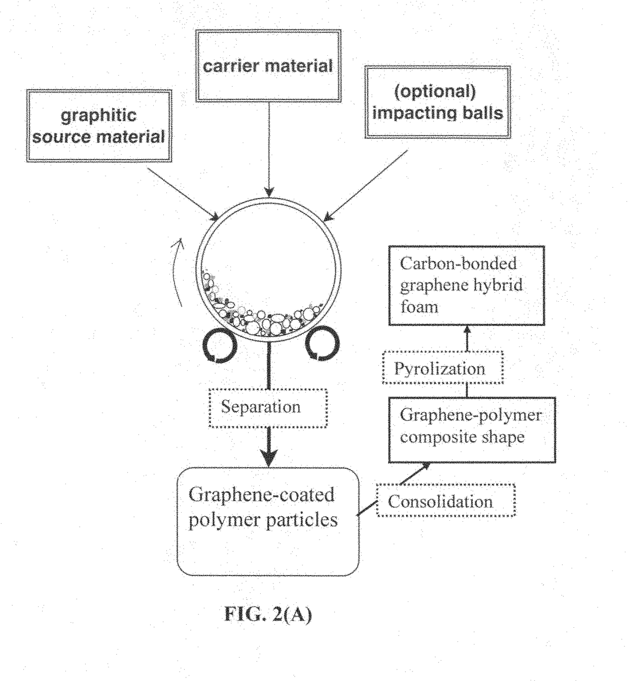
The present invention provides a method for making a 3D graphene-carbon foam by heating a mixture of graphite particles and polymer particles. This foam has a continuous network of carbon-bonded graphene sheets, allowing for the transfer of electrons and phonons between sheets without interruptions. When heated at higher temperatures, the foam can further be converted into a highly thermally and electrically conductive material. The resulting material has high thermal conductivity and electrical conductivity, making it useful for thermal management applications.

Problems solved by technology

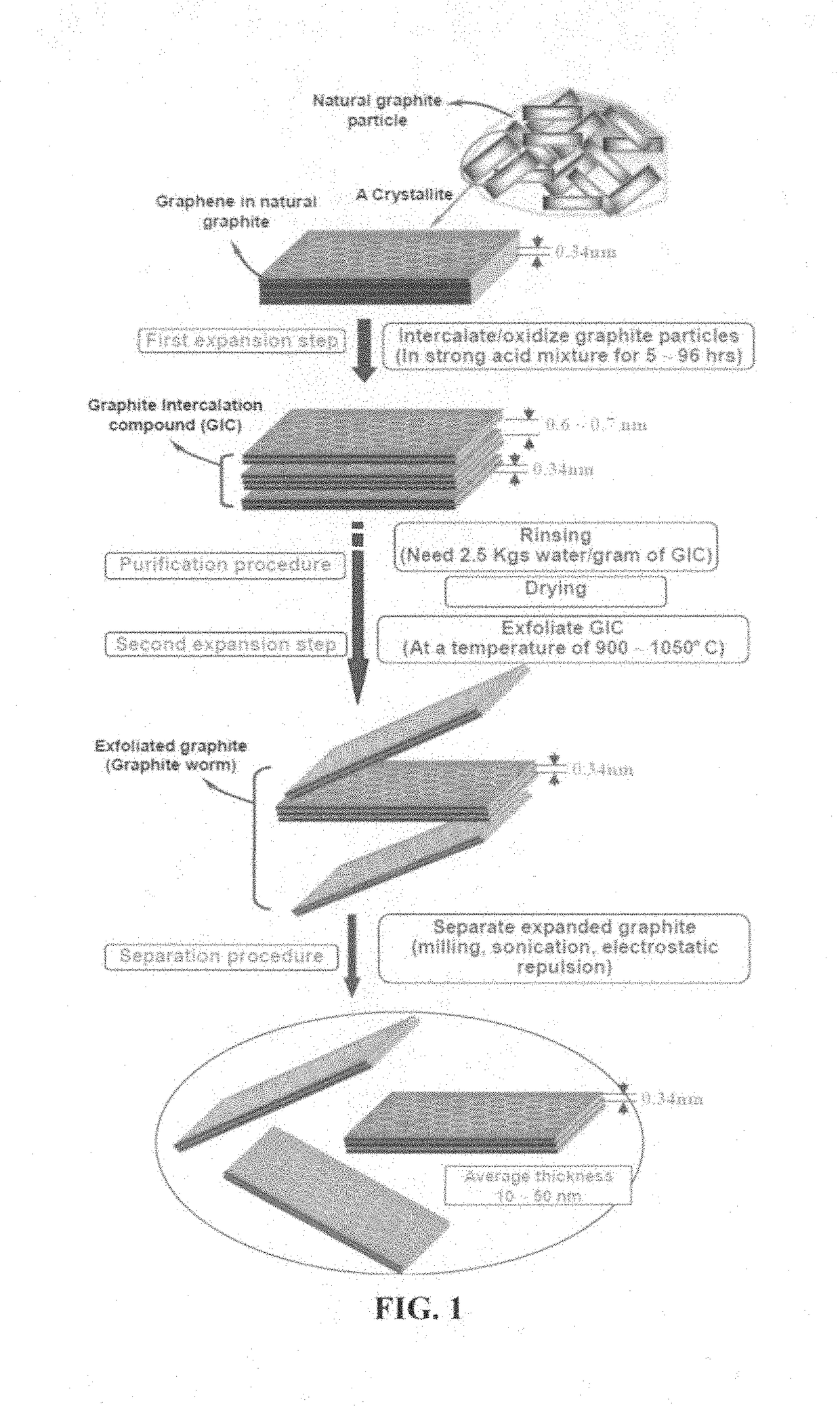
There are several major problems associated with this conventional chemical production process:(1) The process requires the use of large quantities of several undesirable chemicals, such as sulfuric acid, nitric acid, and potassium permanganate or sodium chlorate.(2) The chemical treatment process requires a long intercalation and oxidation time, typically 5 hours to five days.(3) Strong acids consume a significant amount of graphite during this long intercalation or oxidation process by “eating their way into the graphite” (converting graphite into carbon dioxide, which is lost in the process).
It is not unusual to lose 20-50% by weight of the graphite material immersed in strong acids and oxidizers.(4) The thermal exfoliation requires a high temperature (typically 800-1,200° C.) and, hence, is a highly energy-intensive process.(5) Both heat- and solution-induced exfoliation approaches require a very tedious washing and purification step.
During the high-temperature exfoliation, the residual intercalate species retained by the flakes decompose to produce various species of sulfuric and nitrous compounds (e.g., NOx and SOx), which are undesirable.
The process must be carefully conducted in a vacuum or an extremely dry glove box environment since pure alkali metals, such as potassium and sodium, are extremely sensitive to moisture and pose an explosion danger.
This process is not amenable to the mass production of NGPs.
However, these processes are not suitable for mass production of isolated graphene sheets for composite materials and energy storage applications.
The Ni- or Cu-catalyzed CVD process does not lend itself to the deposition of more than 5 graphene planes (typically <2 nm) beyond which the underlying Ni or Cu layer can no longer provide any catalytic effect.
The CVD graphene films are extremely expensive.
This is a slow process that thus far has produced very small graphene sheets.
There are several major issues associated with this method: (a) The high pressure requirement makes it an impractical method for industrial-scale production.
For one thing, this process cannot be conducted on a continuous basis.
(b) It is difficult, if not impossible, to exercise control over the pore size and the porosity level of the resulting porous structure.
(c) There is no flexibility in terms of varying the shape and size of the resulting reduced graphene oxide (RGO) material (e.g. it cannot be made into a film shape).
Furthermore, it is practically impossible to operate a 1000-liter reactor that has to withstand the conditions of a high temperature and a high pressure.
Clearly, this is not a scalable process for mass production of porous graphene structures.
There are several problems associated with such a process: (a) the catalytic CVD is intrinsically a very slow, highly energy-intensive, and expensive process; (b) the etching agent is typically a highly undesirable chemical and the resulting Ni-containing etching solution is a source of pollution.
It is very difficult and expensive to recover or recycle the dissolved Ni metal from the etchant solution.
(c) It is challenging to maintain the shape and dimensions of the graphene foam without damaging the cell walls when the Ni foam is being etched away.
The resulting graphene foam is typically very brittle and fragile.
(d) The transport of the CVD precursor gas (e.g. hydrocarbon) into the interior of a metal foam can be difficult, resulting in a non-uniform structure, since certain spots inside the sacrificial metal foam may not be accessible to the CVD precursor gas.
This method also has several shortcomings: (a) This method requires very tedious chemical treatments of both graphene oxide and PS particles.
(b) The removal of PS by toluene also leads to weakened macro-porous structures.
(d) The pore sizes are typically excessively big (e.g. several μm), too big for many useful applications.
The above discussion clearly indicates that every prior art method or process for producing graphene foams has major deficiencies.

Method used


Image

  • Integral 3D graphene-carbon hybrid foam and devices containing same
  • Integral 3D graphene-carbon hybrid foam and devices containing same
  • Integral 3D graphene-carbon hybrid foam and devices containing same

Examples


example 1

n of Graphene-Carbon Foam from Flake Graphite Via Polypropylene Powder-Based Solid Polymer Carrier

[0132]In an experiment, 1 kg of polypropylene (PP) pellets, 50 grams of flake graphite, 50 mesh (average particle size 0.18 mm; Asbury Carbons, Asbury N.J.) and 250 grams of magnetic steel balls were placed in a high-energy ball mill container. The ball mill was operated at 300 rpm for 2 hours. The container lid was removed and stainless steel balls were removed via a magnet. The polymer carrier material was found to be coated with a dark graphene layer. Carrier material was placed over a 50 mesh sieve and a small amount of unprocessed flake graphite was removed.

[0133]A sample of the coated carrier material was then immersed in tetrachloroethylene at 80° C. for 24 hours to dissolve PP and allow graphene sheets to disperse in the organic solvent. After solvent removal, isolated graphene sheet powder was recovered (mostly few-layer graphene). The remaining coated carrier material was then...

example 2

Carbon Hybrid Foam Using Expanded Graphite (>100 nm in Thickness) as the Graphene Source and ABS as the Polymer Solid Carrier Particles

[0136]In an experiment, 100 grams of ABS pellets, as solid carrier material particles, were placed in a 16 oz plastic container along with 5 grams of expanded graphite. This container was placed in an acoustic mixing unit (Resodyn Acoustic mixer) and processed for 30 minutes. After processing, carrier material was found to be coated with a thin layer of carbon. A small sample of carrier material was placed in acetone and subjected to ultrasound energy to speed dissolution of the ABS. The solution was filtered using an appropriate filter and washed four times with additional acetone. Subsequent to washing, filtrate was dried in a vacuum oven set at 60° C. for 2 hours. This sample was examined by optical microscopy and found to be graphene. The remaining pellets were extruded to create graphene-polymer sheets (1 mm thick), which were then carbonized to...

example 3

n of Graphene-Carbon Hybrid Foam from Meso-Carbon Micro Beads (MCMBs as the Graphene Source Material)) and Polyacrylonitrile (PAN) Fibers (as Solid Carrier Particles)

[0137]In one example, 100 grams of PAN fiber segments (2 mm long as the carrier particles), 5 grams of MCMBs (China Steel Chemical Co., Taiwan), and 50 grams of zirconia beads were placed in a vibratory ball mill and processed for 2 hours. After the process was completed, the vibratory mill was then opened and the carrier material was found to be coated with a dark coating of graphene sheets. The zirconia particles, having distinctly different sizes and colors were manually removed. The graphene-coated PAN fibers were then compacted and melted together to form several composite films. The films were subjected to a heat treatment at 250° C. for 1 hour (in room air), 350° C. for 2 hours, and 1,000° C. for 2 hours (under an argon gas atmosphere) to obtain graphene-carbon foam layers. Half of the carbonized foam layers were...


PUM

PropertyMeasurementUnit
weight ratioaaaaaaaaaa
densityaaaaaaaaaa
pore sizeaaaaaaaaaa

Abstract

Provided is an integral 3D graphene-carbon hybrid foam composed of multiple pores and pore walls, wherein the pore walls contain single-layer or few-layer graphene sheets chemically bonded by a carbon material having a carbon material-to-graphene weight ratio from 1 / 100 to 1 / 2, wherein the few-layer graphene sheets have 2-10 layers of stacked graphene planes having an inter-plane spacing d002 from 0.3354 nm to 0.40 nm and the graphene sheets contain a pristine graphene material having essentially zero % of non-carbon elements, or a non-pristine graphene material having 0.01% to 25% by weight of non-carbon elements wherein said non-pristine graphene is selected from graphene oxide, reduced graphene oxide, graphene fluoride, graphene chloride, graphene bromide, graphene iodide, hydrogenated graphene, nitrogenated graphene, doped graphene, chemically functionalized graphene, or a combination thereof. Also provided are a process for producing the hybrid form, products containing the hybrid foam, and its applications.

Description

FIELD OF THE INVENTION[0001]The present invention relates generally to the field of carbon / graphite foams and, more particularly, to a new form of porous graphitic material herein referred to as an integral 3D graphene-carbon hybrid foam, a process for producing same, products containing same, and a method of operating the product.BACKGROUND OF THE INVENTION[0002]Carbon is known to have five unique crystalline structures, including diamond, fullerene (0-D nano graphitic material), carbon nano-tube or carbon nano-fiber (1-D nano graphitic material), graphene (2-D nano graphitic material), and graphite (3-D graphitic material). The carbon nano-tube (CNT) refers to a tubular structure grown with a single wall or multi-wall. Carbon nano-tubes (CNTs) and carbon nano-fibers (CNFs) have a diameter on the order of a few nanometers to a few hundred nanometers. Their longitudinal, hollow structures impart unique mechanical, electrical and chemical properties to the material. The CNT or CNF is...

Claims


Application Information

Patent Timeline
Patent Type & Authority Applications(United States)
IPC IPC(8): B01J20/20B01D15/08C09K5/14C02F1/28B01J20/28C09K3/32
CPCB01J20/20B01J20/28045B01J20/28059B01J20/28061B01J20/28064B01J20/28066C02F2303/16C09K3/32C09K5/14C02F1/283B01D15/08C02F2101/32B01J20/28083B01J20/205B01J20/28011C02F1/681
Inventor ZHAMU, ARUNAJANG, BOR Z.
Owner GLOBAL GRAPHENE GRP INC
Learn More