
Radiation detector for use as an image intensifier

Inactive Publication Date: 2017-06-22
GENERAL ELECTRIC CO
View PDF9 Cites 1 Cited by
  • Summary
  • Abstract
  • Description
  • Claims
  • Application Information

AI Technical Summary

Benefits of technology

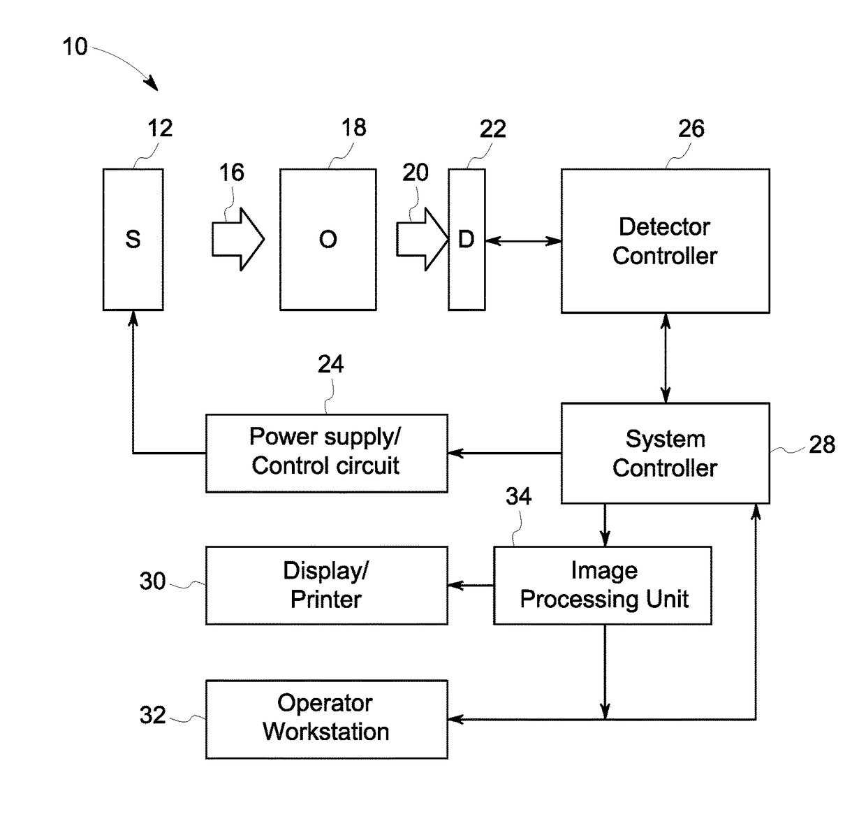
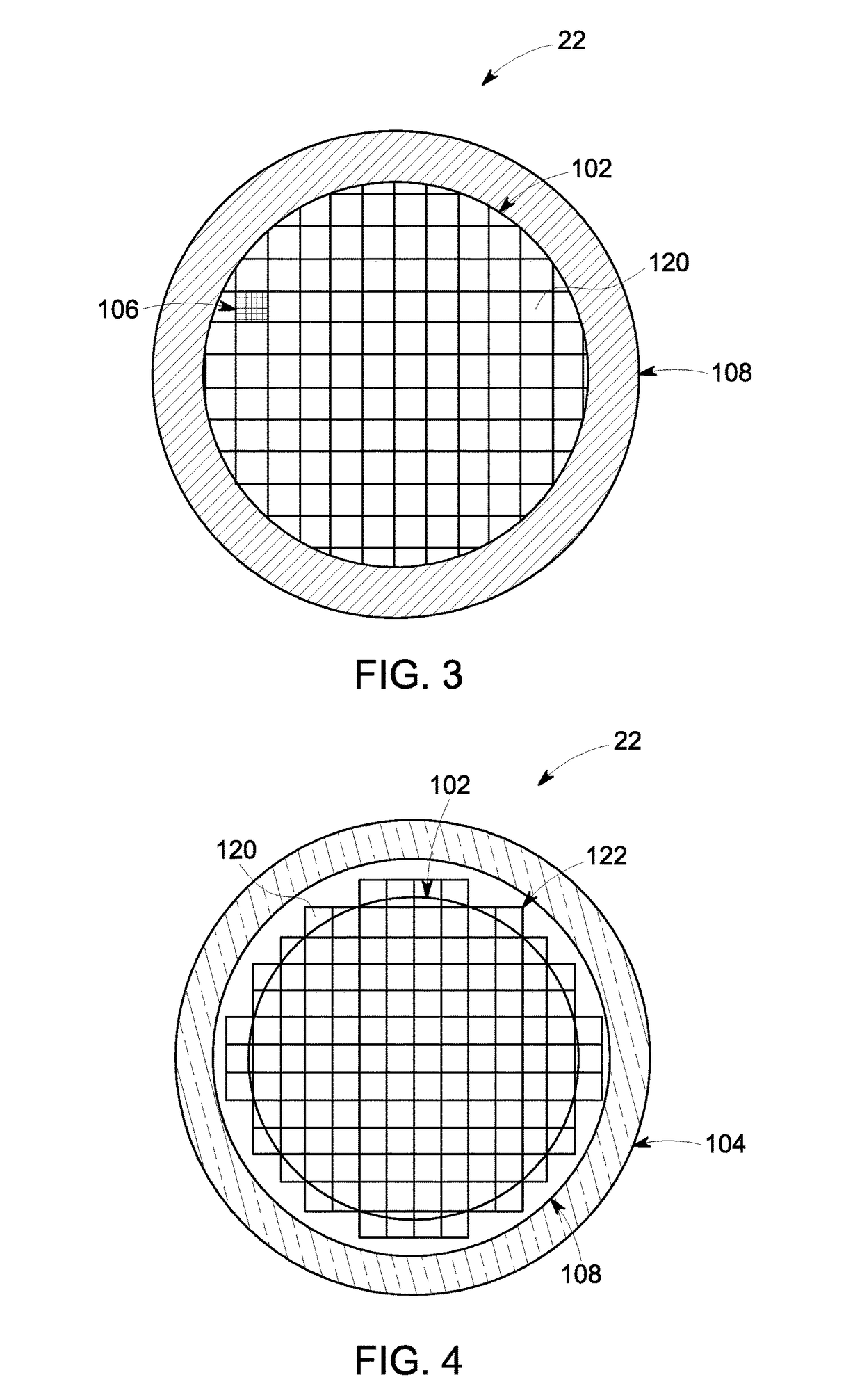
The patent describes a radiation detector comprising a panel of complementary metal-oxide-semiconductor (CMOS) tiles that form a circular light sensing panel. The detector is used in an X-ray imaging system with an X-ray source, a flat panel detector, and an image processing unit. The image processing unit applies a digital mask to mask out the value of pixels outside the active area, yielding the circular shape images. The technical effect is a more efficient and accurate detection of X-rays, allowing for improved image quality and reduced radiation dose. Another technical effect is the emulation of an image intensifier using the flat panel detector and the availability of different magnification modes. Additionally, a method of exchanging system commands for the image intensifier to commands for the flat panel detector and applying a digital mask to the obtained image is provided.

Problems solved by technology

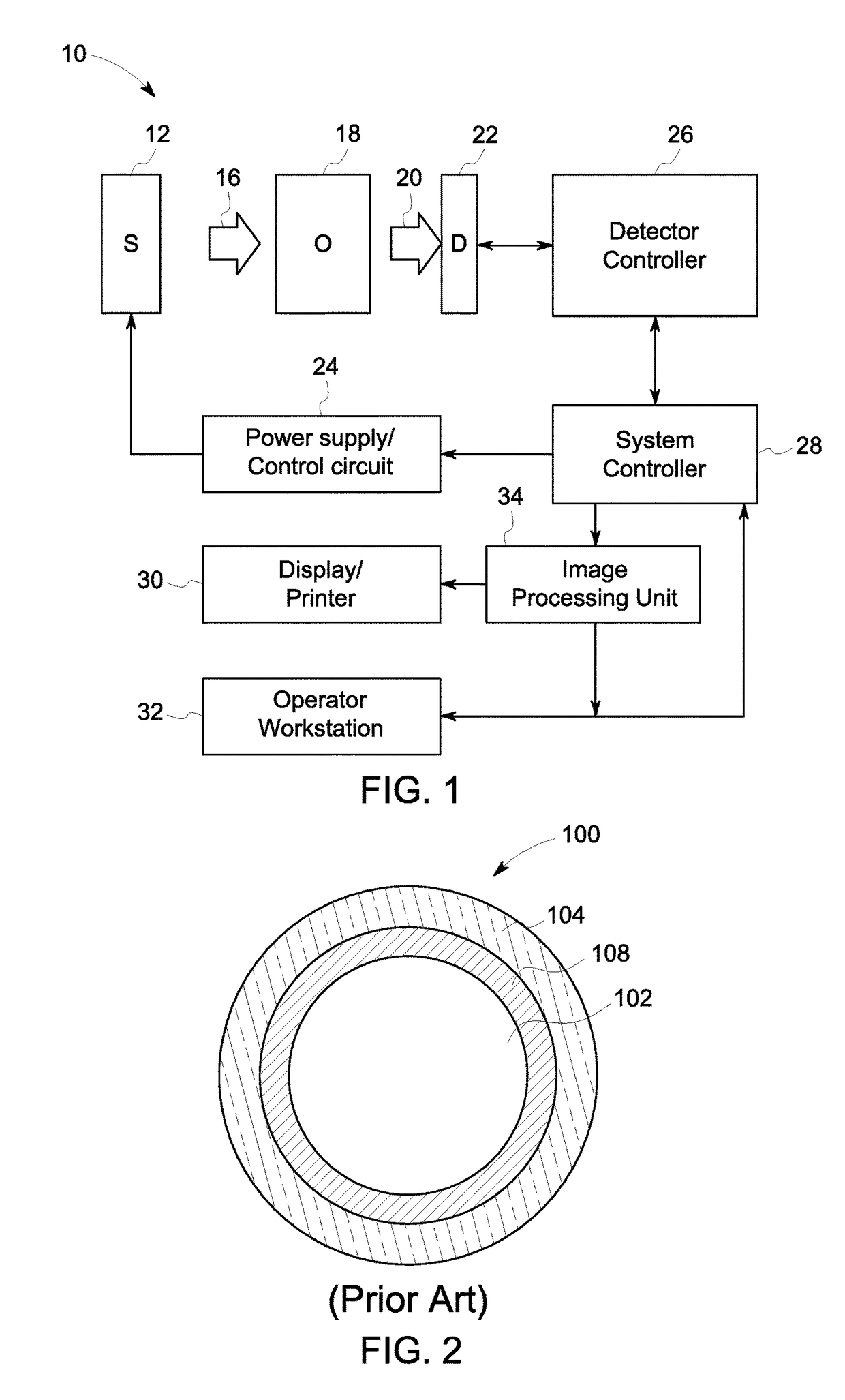
One obstacle to replacing image intensifiers in legacy systems with newer radiation detector technology is the form factor of the image intensifiers in the installed base of devices.
Thus, replacing the existing circular cross-section image intensifiers with square or rectangular flat panel detectors is not a straight-forward operation if it is desired to maintain the existing cylindrical form factor.

Method used


Image

  • Radiation detector for use as an image intensifier
  • Radiation detector for use as an image intensifier
  • Radiation detector for use as an image intensifier

Examples


Embodiment Construction

[0014]One or more specific implementations will be described below. In an effort to provide a concise description of these implementations, not all features of an actual implementation are described in the specification. It should be appreciated that in the development of any such actual implementation, as in any engineering or design project, numerous implementation-specific decisions must be made to achieve the developers' specific goals, such as compliance with system-related and business-related constraints, which may vary from one implementation to another. Moreover, it should be appreciated that such a development effort might be complex and time consuming, but would nevertheless be a routine undertaking of design, fabrication, and manufacture for those of ordinary skill having the benefit of this disclosure.

[0015]When introducing elements of various embodiments of the present subject matter, the articles “a,”“an,”“the,” and “said” are intended to mean that there are one or mo...


PUM


Abstract

A flat panel detector is provided having a circular active area. The flat panel detector is built using complementary metal-oxide-semiconductor (CMOS) tiles. In one implementation, the flat panel detector having a circular active area can be used as a replacement for a conventional image intensifier, including an image intensifier used in a fluoroscopy system.

Description

BACKGROUND[0001]The subject matter disclosed herein relates to X-ray imaging and, in particular, to the fabrication and use of a tiled radiation detector as a radiological imaging unit consisting of an X-ray image intensifier and a CCD (charge-coupled device) camera. For the sake of simplicity, the term image intensifier, when used herein, refers to the entire radiological imaging unit.[0002]Non-invasive imaging technologies allow images of the internal structures or features of a patient or object to be obtained without performing an invasive procedure on the patient or object. In particular, such non-invasive imaging technologies rely on various physical principles, such as the differential transmission of X-rays through the target volume or the reflection of acoustic waves, to acquire data and to construct images or otherwise represent the observed internal features of the patient or object.[0003]For example, in fluoroscopy and other X-ray based imaging technologies, X-ray radiat...

Claims


Application Information

Patent Timeline
IPC IPC(8): H01L27/146G01N23/04G01T1/24
CPCH01L27/14663G01N23/043G01T1/247G01N2223/501
Inventor JACOB, BIJULIU, JAMES ZHENGSHE
Owner GENERAL ELECTRIC CO
Learn More