Electronic terminal equipment and method for assembling same

Inactive Publication Date: 2017-03-30
KANEKA CORP
View PDF20 Cites 16 Cited by
  • Summary
  • Abstract
  • Description
  • Claims
  • Application Information

AI Technical Summary

Benefits of technology

The present invention aims to provide an electronic terminal equipment that is compact and thin without compromising its functionality. The invention prevents overheating of the electronic equipment, reduces heat spots, and lowers the temperature of the heat-generating electronic component, thereby extending its lifespan. The invention also ensues efficient heat dissipation and reduces thermal contact resistance, resulting in high efficiency of heat release.

Problems solved by technology

With such performance improvements of computing devices, communication control devices, storage devices, etc., the amounts of heat generated from these devices have also increased significantly and that often causes malfunction of the electronic terminal equipments.
Moreover, while performances of the computing devices, communication control devices, storage devices, etc., and amounts of generated heat are thus increasing, product packages are becoming smaller and thinner year by year, and therefore heat can hardly radiate from the electronic terminal equipments.
Also, front surfaces of most heat-generating electronic components are not smooth and therefore the heat dissipation member cannot be placed in close contact with the heat-generating electronic component and a substantial contact area between the heat-generating electronic component and the heat dissipation member is reduced.
As described above, the heat dissipation performance by heat dissipation members cannot function sufficiently and consequently, satisfactory temperature reduction is not obtained.

Method used


Image

  • Electronic terminal equipment and method for assembling same
  • Electronic terminal equipment and method for assembling same
  • Electronic terminal equipment and method for assembling same

Examples


synthesis example 1

Resin Synthesis Example 1

[0099]Under a nitrogen atmosphere, CuBr (1.09 kg), acetonitrile (11.4 kg), butyl acrylate (26.0 kg), and diethyl 2,5-dibromoadipate (2.28 kg) were added to a 250 L reactor and stirred for approximately 30 minutes at 70 to 80° C. Pentamethyldiethylenetriamine was added to the above to start a reaction. From 30 minutes after the start of reaction, butyl acrylate (104 kg) was added continuously over a period of 2 hours. Pentamethyldiethylenetriamine was added as suitable during the reaction to keep the internal temperature at 70° C. to 90° C. The total amount of pentamethyldiethylenetriamine used up to this point was 220 g. After 4 hours from the start of reaction, volatile matter was removed by heating and stirring at 80° C. under reduced pressure. Acetonitrile (45.7 kg), 1,7-octadiene (14.0 kg), and pentamethyldiethylenetriamine (439 g) were then added thereto and stirring was continued for 8 hours. The mixture was heated and stirred at 80° C. under reduced p...

synthesis example 2

Resin Synthesis Example 2

[0105]Using polyoxypropylene diol with a number average molecular weight of approximately 2,000 as an initiator, propylene oxide was polymerized with a zinc hexacyanocobaltate-glyme complex catalyst to obtain polypropylene oxide with a number average molecular weight of 25,500 (polystyrene equivalent value measured using HLC-8120 GPC, made by Tosoh Corporation, as the liquid feeding system, using TSK-GEL H Type, made by Tosoh Corporation, as the column, and using THF as the solvent). Subsequently, NaOMe methanol solution of 1.2 times equivalent of the hydroxyl groups of the hydroxyl-group-terminated polypropylene oxide was added, the methanol was distilled off, and allyl chloride was added to convert the hydroxyl groups at the terminal to allyl groups. The unreacted allyl chloride was removed by reduced pressure devolatilization. With respect to 100 parts by weight of the obtained unrefined allyl-group-terminated polypropylene oxide, 300 parts by weight of n...

examples 1 to 5

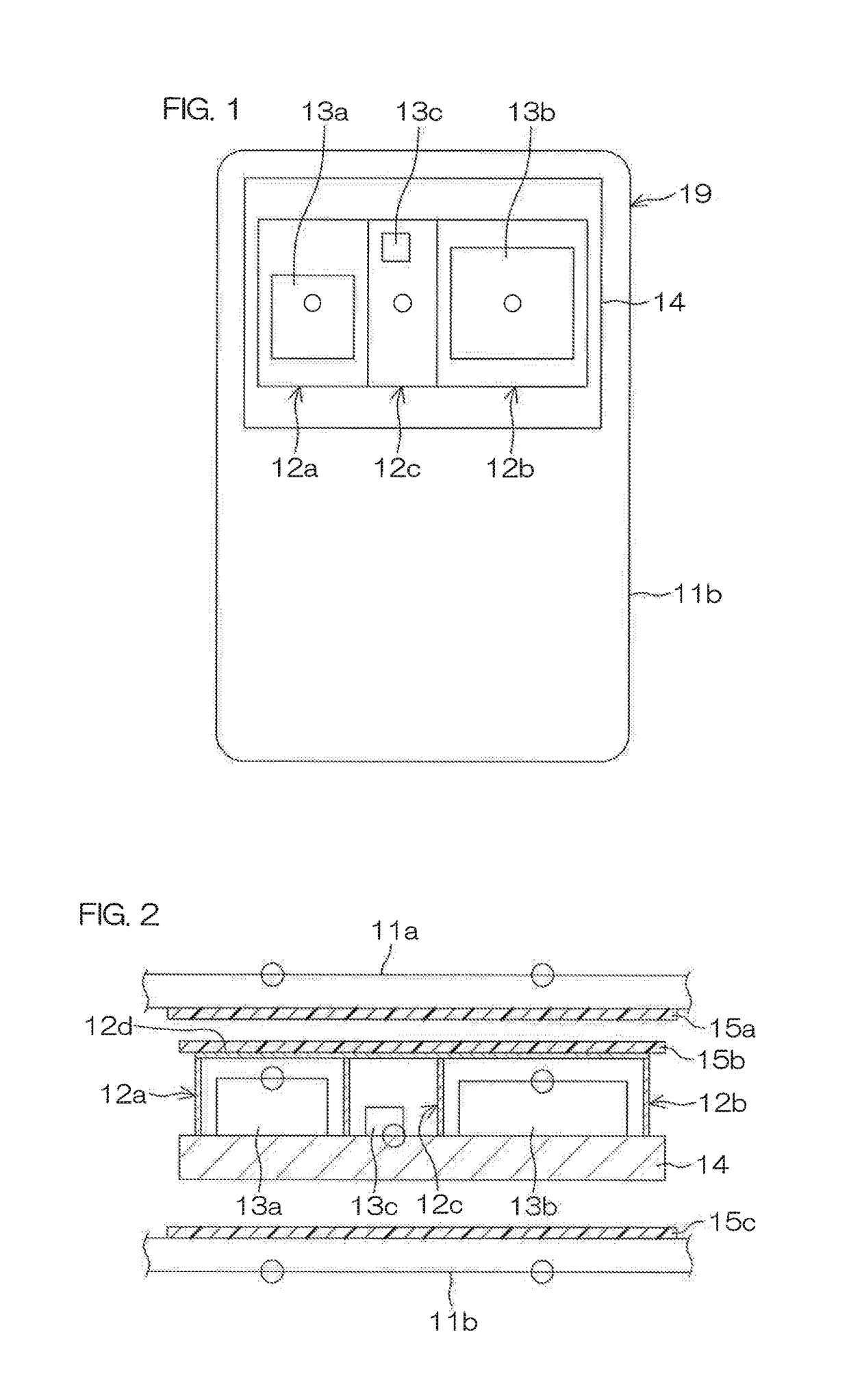
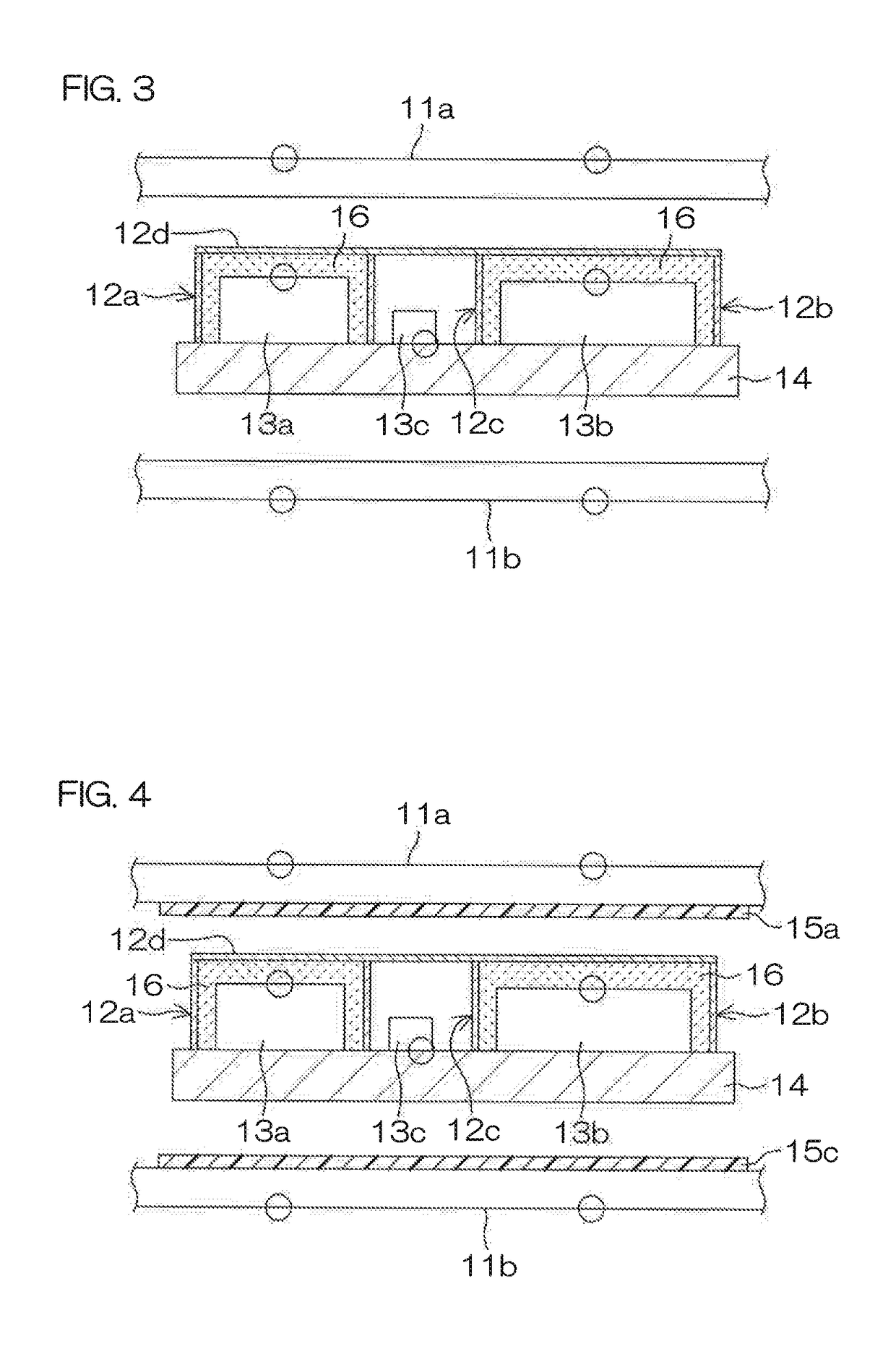
[0129]The portion 11a of the casing of the smart phone 19 was removed to expose the substrate 14, the upper surfaces 12d of the electromagnetic shield members 12a and 12b on the substrate were removed, filling and curing of a thermally-conductive curable liquid resin 16 were performed, the electromagnetic shield member b was capped with the upper surfaces 12d, and a highly thermally-conductive resin film was disposed at an inner side of the casing 11a and / or the upper surfaces 12d of the electromagnetic shield members.

[0130]FIG. 4 is a sectional view where, the upper surfaces 12d of the electromagnetic shield members that surround the heat-generating electronic components 13a and 13b were removed, and above the substrate 14, the thermally-conductive curable liquid resin 16 was filled and cured between the electromagnetic shield members 12a and 12b and the substrate 14 so as to contact the heat-generating electronic components 13a and 13b. Then the electromagnetic shield members were...


PUM


Abstract

The electronic terminal equipment comprising an electronic substrate on which a heat-generating electronic component is mounted and an electromagnetic shield member attached in proximity to the heat-generating electronic component, the electronic substrate being filled with a cured product of a thermally-conductive curable liquid resin between the electromagnetic shield member and the electronic substrate, and a thermally-conductive film being disposed in contact with an upper surface of the electromagnetic shield member or facing the upper surface thereof so as to diffuse heat that came up through the cured thermally-conductive curable liquid resin.

Description

TECHNICAL FIELD[0001]The present invention relates to electronic terminal equipment and a method for assembling the same.BACKGROUND ART[0002]In recent years, various functions of electronic terminal equipments, such as personal computers, tablet terminals, cellular phones, smart phones, PDAs, etc., have been realized and they are due to improvements of performances of incorporated computing devices (for example, CPUs and GPUs), communication control devices (for example, base band processors), storage devices (for example, DRAMs), etc therein.[0003]With such performance improvements of computing devices, communication control devices, storage devices, etc., the amounts of heat generated from these devices have also increased significantly and that often causes malfunction of the electronic terminal equipments.[0004]Moreover, while performances of the computing devices, communication control devices, storage devices, etc., and amounts of generated heat are thus increasing, product pa...

Claims


Application Information

Patent Timeline
IPC IPC(8): G06F1/20H05K3/28H05K1/18H05K1/02H05K9/00H05K7/20
CPCG06F1/203H05K9/0024H05K7/20409H05K1/181H05K2203/1322H05K3/284H05K3/285H05K2201/10371H05K2203/1316H05K1/0203H01L2924/0002H05K7/20463G06F1/1656H05K9/0032H01L2924/00
Inventor KOUKAMI, AKINISHIURA, KOICHINAKAGAKI, TAKESHI
Owner KANEKA CORP
Why Eureka
Try Eureka