In-vehicle engine control apparatus

a technology for control apparatus and engine, which is applied in the direction of electric control, heat measurement, instruments, etc., can solve the problems of increasing cost and vehicle weight, increasing the cost and weight of the vehicle, and affecting so as to achieve advantageously reduce the control load of the microprocessor and improve the combustion characteristic of the fuel

Active Publication Date: 2017-03-30
MITSUBISHI ELECTRIC CORP
View PDF0 Cites 8 Cited by
  • Summary
  • Abstract
  • Description
  • Claims
  • Application Information

AI Technical Summary

Benefits of technology

[0051]Therefore, it is advantageous that in case a specific switch element becomes excessively higher in temperature than other switch elements, the temperature suppressing means for the specific switch elements is added improve the combustion characteristic of fuel by making the split injection frequency higher.
[0052]Also, the value of the allowable split injection frequency is based on statistic data preliminarily obtained from experimental measurements by a plurality of in-vehicle engine control apparatuses, requiring no estimation of the internal temperature of the element to be monitored during real machine operations, and a plurality of elements to be monitored can be collectively monitored, so that the control load of the microprocessor can be advantageously reduced.

Problems solved by technology

Therefore, in case where the fuel injection amount required is small, requiring no valve opening-holding period, and the power feeding is stopped immediately after the rapid power feeding current has attenuated, the heat amount generated in the injector driving circuit 22 by the control B is apparently smaller than that by control A, so that it is not simply possible to specify what level of attenuation cutoff current would make the control B more disadvantageous.
Therefore, there is a problem that the internal temperature rise allowed for the switch element in the inside of the fuel injection control apparatus becomes 20-30 degrees C. or less, and that even though the temperature at the nearest position of the switch element is detected, its distribution between the environmental temperature and the temperature rise due to the self-heat generation is not detected, so that the temperature rise component of the switch element cannot be accurately controlled, and that even if the temperature rise is actually much smaller, a control only with a margin based on the highest temperature rise for the worst condition scenario.
Therefore, there is a problem that the cost and the vehicle weight increase as the number of external wiring increases, and that the contact reliability is lowered due to the increase of pin number of connector, and an occurrence probability of disconnection / short-circuit a ground fault contacting the ground circuit of external wirings, or an abnormal sky fault connection thereof with the positive side wiring of the power supply grows.
Therefore, there is a problem that while if the engine rotational speed is assumed to be acquired by thermal information acquiring means, the temperature rise of e.g. the boosting switch element can be estimated from the engine rotational speed, but the temperature of the boosting switch element itself cannot be estimated if the environmental temperature is not known.
Also, there is a problem that even though the engine rotational speed is determined, the temperature rise itself of the switch element which supplies the valve opening-holding current cannot be estimated.
Also, there is a problem that if the thermal sensor is made a thermal information acquiring means and if the thermal sensor detects the temperature of the nearest position of the heat generated element, the distinction between the environmental temperature and the temperature rise due to the self-generated heat cannot be made, so that if it is provided at a position far from the heat generated element, the temperature of the heat generated element itself cannot be estimated.
While FIG. 5 of Patent Document 2 determines an applicable control mode with a dual map of the detected temperature by the thermal sensor and the engine rotational speed upon attending to the above problem, a plurality of switch elements in the driving circuits are not individually focused, so that individual accurate determination cannot be made and only a general determination having a certain margin can be done.
On the other hand, there is a problem that in “Driving apparatus of electromagnetic load” according to the above Patent Document 3, the number of use of the power feeding-sustaining switch elements T11, T21, the rapid excitation switch elements T12, T22, and the boosting switch element 100 is fewer than the number of use of the rapid cutoff switch elements T10-T40, sharing a plurality of solenoids, so that the power loss is concentrated and the temperature rise of the local part becomes excessive.
Also, there is a problem that while the regenerative charging system for suppressing the temperature rise of the rapid cutoff switch elements T10-T40 and the boosting switch element T100 is applied, complicated adjusting means for stabilizing the valve opening characteristics is required.

Method used


Image

  • In-vehicle engine control apparatus
  • In-vehicle engine control apparatus
  • In-vehicle engine control apparatus

Examples


embodiment 1

(1) Detailed Description of Arrangement

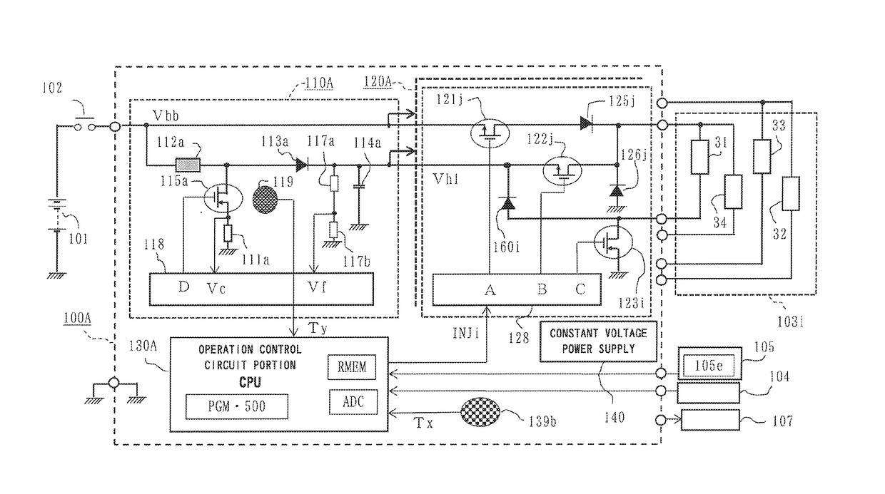
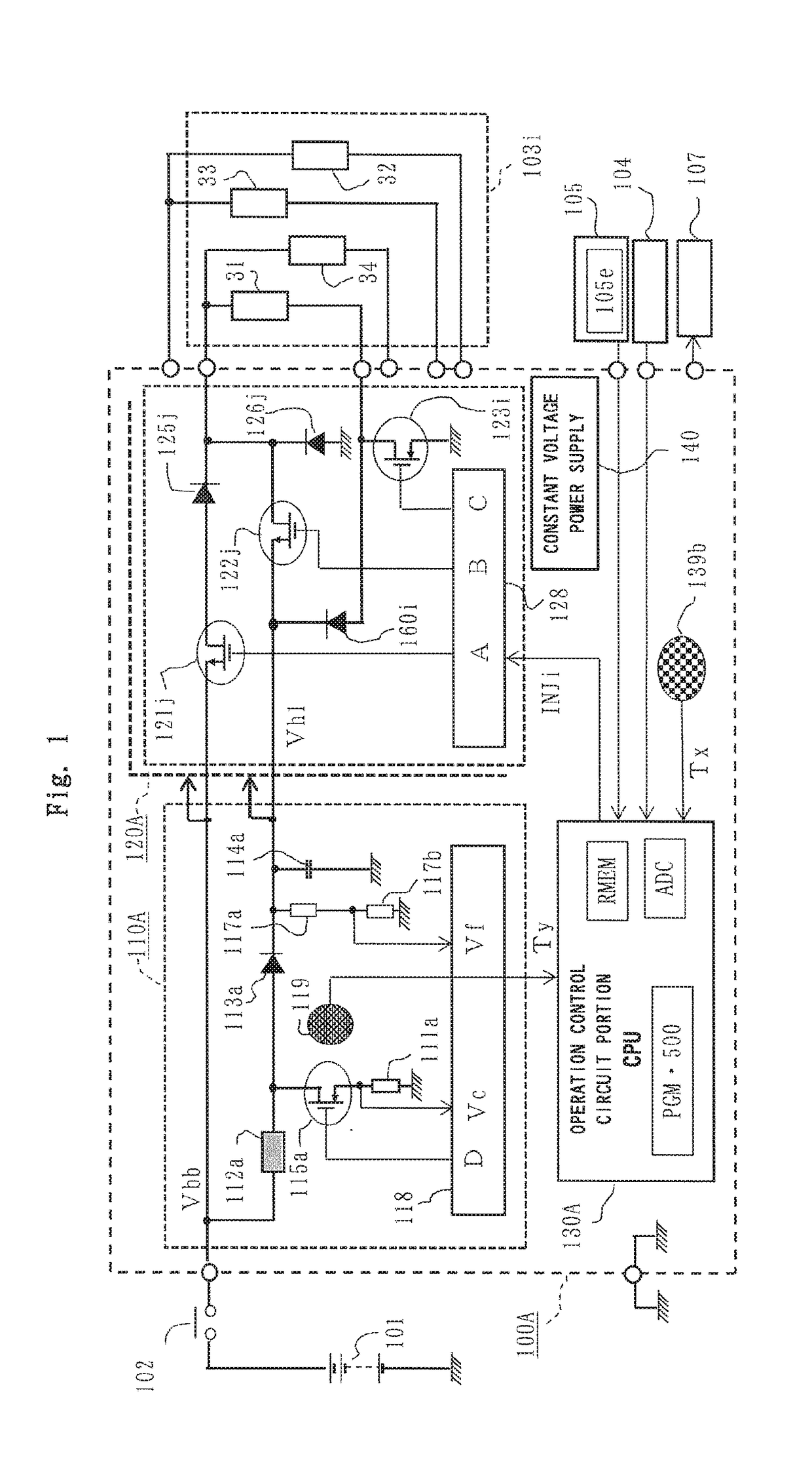
[0067]Firstly, an arrangement of FIG. 1 showing an entire electric circuit of an in-vehicle engine control apparatus according to Embodiment 1 of the present invention will be described.

[0068]In FIG. 1, an in-vehicle engine control apparatus 100A is mainly composed of a drive control circuit portion 120A for electromagnetic coils 103i (hereinafter, occasionally referred to as electromagnetic coil 103i in a singular form) of fuel injection electromagnetic valves provided in association with cylinder numbers i=1, 2, m of a multi-cylinder engine, a boosting control circuit portion 110A forming a high voltage power supply for rapidly exciting the electromagnetic coils 31-34, and an operation control circuit portion 30A composed of an integrated circuit element of one chip or two chips together with the boosting control circuit portion 110A, and a constant voltage power supply 140 for supplying a predetermined stabilized voltage to each control circ...

embodiment 2

(1) Detailed Description of Arrangement and Effect

[0230]Hereinafter, the arrangement and the effect will be described referring to FIG. 7 showing the entire circuit block diagram of an in-vehicle engine control apparatus according to Embodiment 2 of the present invention in attention to the difference from the apparatus shown in FIG. 1.

[0231]Throughout the figures the same reference numerals indicate identical or corresponding portions, in which the in-vehicle engine control apparatus 100A is replaced by an in-vehicle engine control apparatus 100B with the alphabet of the capital letter of the reference numeral's tail for indicating each Embodiment.

[0232]In FIG. 7, the first main difference between the apparatus in FIG. 7 and the apparatus in FIG. 1 is that with respect to the four electromagnetic coils 31-34 driving the fuel injection electromagnetic valves, a boosting control circuit portion 110B comprises two induction elements 112a, 112b, two boosting switch elements 115a, 115b ...

embodiment 3

(1) Detailed Description of Arrangement

[0287]Hereinafter, the arrangement and the effect will be described referring to FIG. 8 showing the entire circuit block diagram of an in-vehicle engine control apparatus according to Embodiment 3 of the present invention in attention to the difference with the apparatus shown in FIG. 1.

[0288]Throughout the figures, the same reference numerals indicate identical or corresponding portions, in which the in-vehicle engine control apparatus 100A is replaced by an in-vehicle engine control apparatus 100C with the alphabet of the capital letter of the reference numeral's tail indicating each embodiment.

[0289]In FIG. 8, the first main difference between the apparatus in FIG. 8 and the apparatus in FIG. 1 is that with respect to the four electromagnetic coils 31-34 driving the fuel injection electromagnetic valves, a boosting control circuit portion 110C comprises two induction elements 112a, 112b, two boosting switch elements 115a, 115b intermittently...


PUM

PropertyMeasurementUnit
voltageaaaaaaaaaa
voltageaaaaaaaaaa
voltageaaaaaaaaaa

Abstract

An in-vehicle engine control apparatus allowing split injection frequency or split injection of fuel while preventing a driving switch element for fuel injecting electromagnetic coils and a boosting switch element for generating a boosted high voltage from being overheated. An operation control circuit portion has reference data of measured environmental temperature vs allowable engine rotational speed with a selected value of the split injection frequency being a parameter, and determines the selected value having, as an upper limit, a split injection frequency which makes the internal temperature of the boosting switch element or a rapidly exciting switch element a predetermined allowable limit value in association with the present environmental temperature detected by an average environmental temperature detection element in a case and the present engine rotational speed detected by an engine rotation sensor.

Description

BACKGROUND OF THE INVENTION[0001]1. Field of the Invention[0002]The present invention relates to improvements of an in-vehicle engine control apparatus in which multiple fuel injections, i.e. fuel injections of plural times are performed to the same cylinder in one combustion cycle period of an internal combustion engine, and in particular to an in-vehicle engine control apparatus in which a temperature rise of a fuel injection control portion following such multiple fuel injections is suppressed.[0003]2. Description of the Related Art[0004]A fuel injection type multi-cylinder engine includes a collective injection type which performs the fuel injection once in one combustion cycle period of each cylinder, a split (divided) injection type which performs the fuel injection of the same amount as a whole by multiple split injections, or an intermittent split type which alternately repeats the collective injection and the split injection, in order to improve vehicle exhaust emission mea...

Claims


Application Information

Patent Timeline
Patent Type & Authority Applications(United States)
IPC IPC(8): F02D41/40G01K13/00F02D41/22F02D35/02F02D41/26F02M51/06
CPCF02D41/402F02D41/401F02D41/26F02D2200/021F02D41/22F02D35/02G01K13/00F02M51/06F02D41/30F02D2200/101F02D35/025F02D41/20F02D2041/2065Y02T10/40
Inventor NISHIDA, MITSUNORINISHIZAWA, OSAMUKANZAKI, SHOZO
Owner MITSUBISHI ELECTRIC CORP
Why Eureka
Try Eureka