
Method and device for two-dimensional separation of ionic species

Active Publication Date: 2017-02-02
UNIV REGENSBURG
View PDF0 Cites 2 Cited by
  • Summary
  • Abstract
  • Description
  • Claims
  • Application Information

AI Technical Summary

Benefits of technology

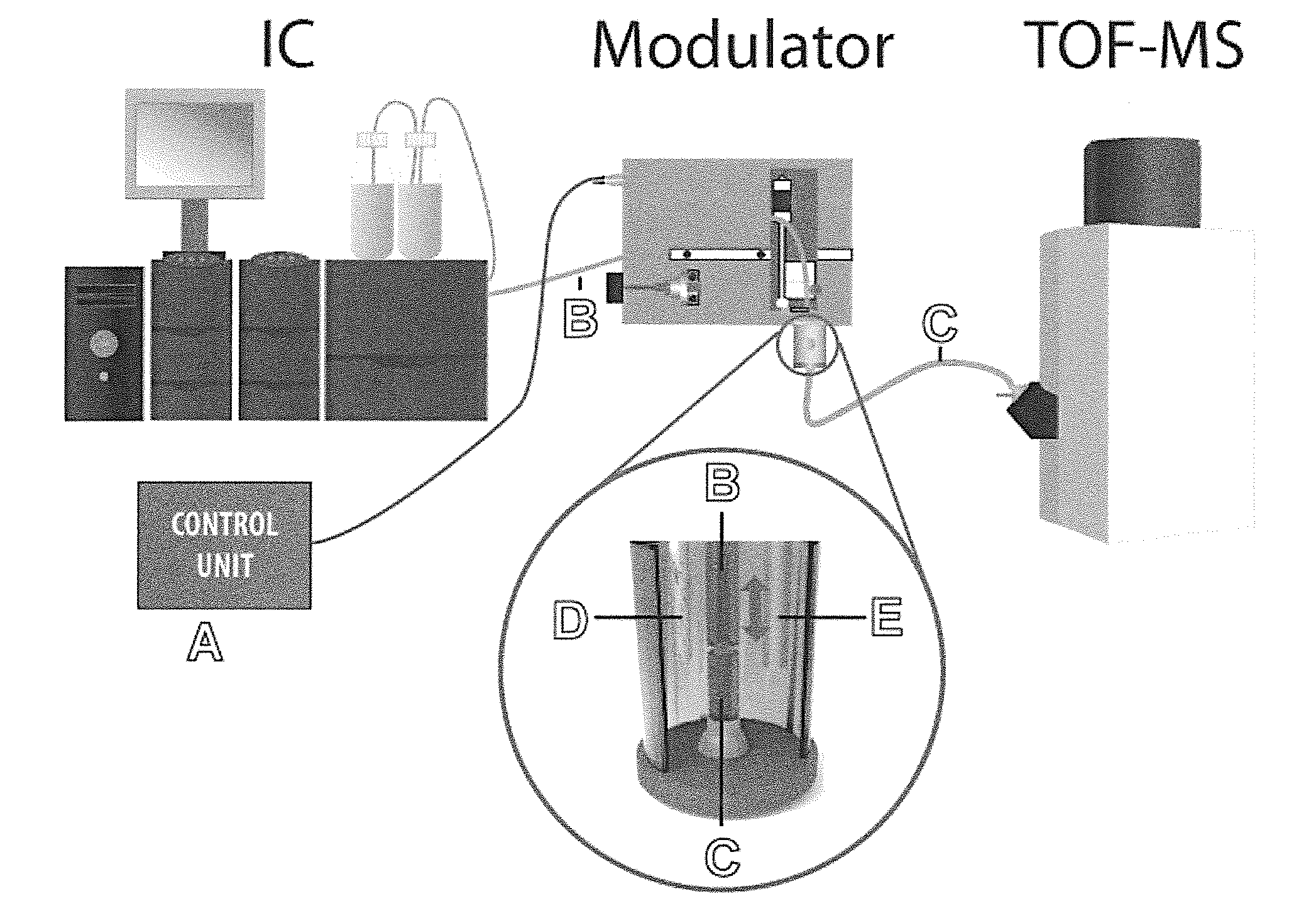
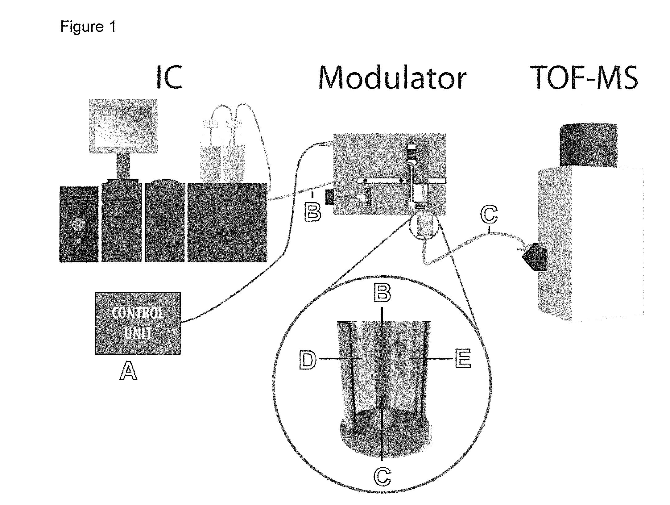
The present invention provides devices and methods for continuous operation of a CE system without interruption of the basic setup. This is achieved by using modulators to control the transfer of the IC carrier flow to the CE system. The new system offers many advantages and can be used to separate charged molecules, like mixtures of nucleotides and cyclic nucleotides, in an efficient manner. In addition, convection in the electrophoresis buffer in the electrolyte vessel can be caused by the movement of the capillary / capillaries, which dilutes the emerging IC carrier flow and minimizes the influence of the IC carrier flow on the stability of the electrophoretic current. This allows using the CE system without the need for stirring, such as a mechanical stirrer in the electrolyte vessel. In another embodiment, a switching valve can be used to control the injection of the IC carrier flow into the separation capillary. This valve can be controlled by a microprocessor and is timed to inject segments of IC carrier flow into the separation capillary. The part of the carrier flow that is not used for CE separation can either be discarded or can flow into the electrolyte vessel. This allows for constant distance between the outlet of the transfer capillary and the infection CE system, and keeps the integrity of the electrophoretic circuit constant.

Problems solved by technology

Although two-dimensional systems were known, a combination of ion exchange chromatography methods and electrophoresis based methods was not contemplated in the past for various reasons.
In particular, the relatively slow separation speed of conventional CE based on the use of long capillaries was deemed to exclude the construction of a corresponding two-dimensional separation system.
Batch processing is labor-intensive and time consuming, as for every batch, the system has to be cleaned and the solutions have to be prepared before the system is ready for the next batch.
Furthermore, batch processing is more error-prone due to being labor-intensive, and comparison of the results of the analysis of the different batch samples can vary due to the practically separate experimental setup conditions for every batch.

Method used


Image

  • Method and device for two-dimensional separation of ionic species
  • Method and device for two-dimensional separation of ionic species
  • Method and device for two-dimensional separation of ionic species

Examples


example 1

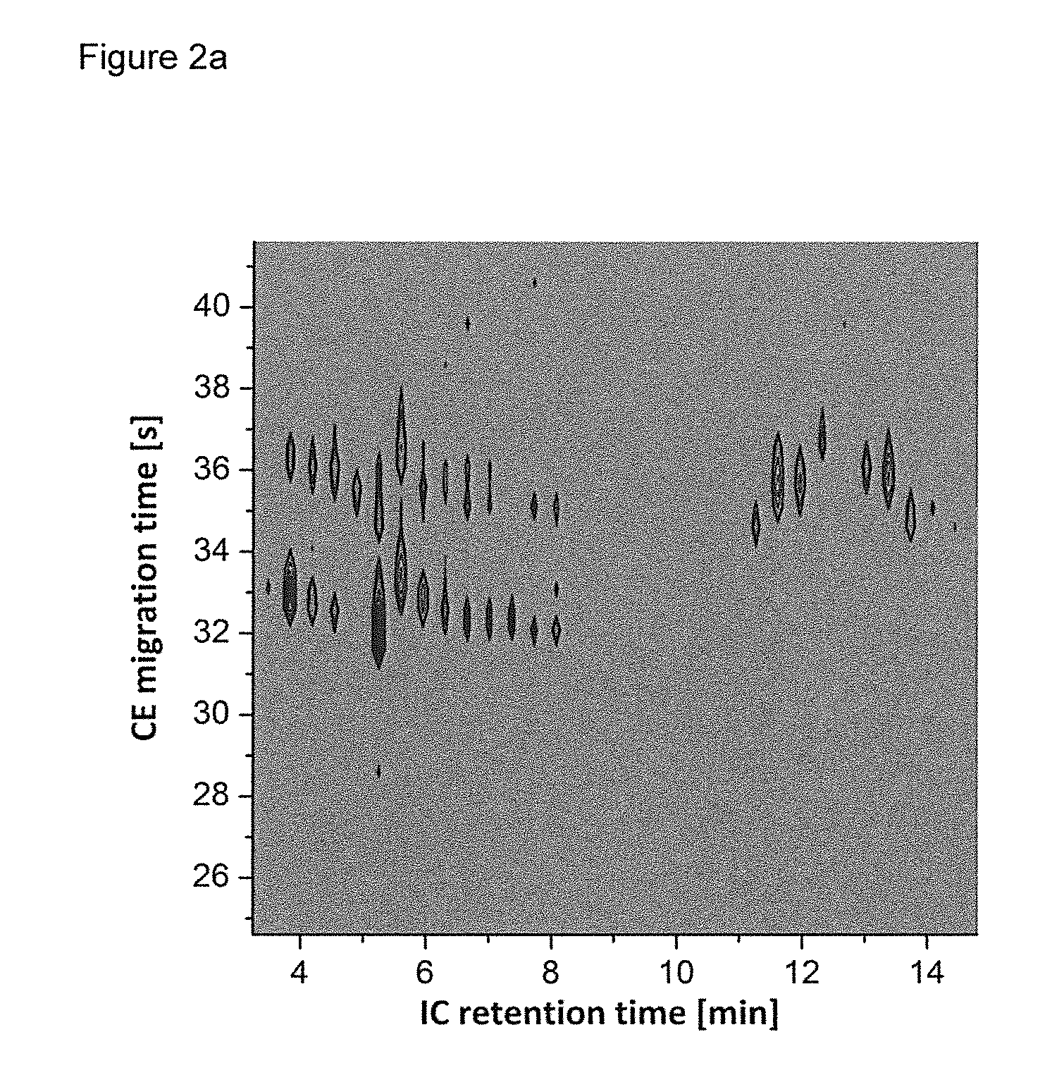
[0073]A sample comprising nucleotides and cyclic nucleotides was subjected to a two-dimensional separation using ion chromatography (IC) and capillary electrophoresis (CE). The IC comprised a suppressor to provide effluent comprising the analytes in highly pure water.

[0074]The sample was injected into the IC system and continuously eluted. The IC effluent was transferred through a non-conductive transfer fused silica capillary to an electrolyte vessel of a CE system containing electrophoresis buffer. Nanoliter volume segments of the effluent were injected into the separation capillary of the CE system by continuously modifying the distance between transfer capillary and separation capillary. The distance between the outlet of the transfer capillary and the inlet of the separation capillary, which were in axial alignment, for injecting a nanoliter volume segment was moved such that the outlet of the transfer capillary had a distance of 50 μm to the inlet of the separation capillary. ...

example 2

[0080]A further sample comprising nucleotides and cyclic nucleotides was subjected to a two-dimensional separation using ion chromatography (IC) and capillary electrophoresis (CE) as described above in Example 1 with the following additional details.

[0081]Prior to using fused silica capillaries (Polymicro Technologies, Phoenix, Ariz., USA) in the separation techniques the capillaries were prepared and conditioned as follows. Both ends of the separation capillary (length=20.5 cm, inner diameter=25 μm) and the injection end of the transfer capillary (length=60 cm, inner diameter=75 μm) were polished with polishing papers (32 μm and 12 μm grit size) at a 90° angle until the surface was smooth. The polyimide coating was removed at a length of about 5 mm. Before each use, the separation capillary was flushed 10 minutes with 100 mM NaOH, 10 minutes with ultrapure water from a Milli-Q system, and 30 minutes with the background electrolyte consisting of a 25 mM ammonium acetate buffer adjus...

example 3

[0087]Modulation times of the IC×CE-MS measurements of a model system comprising a mixture of nucleotides (AMP, GMP, CMP) and cyclic nucleotides (cAMP, cGMP, cCMP) were studied and optimized as illustrated in FIG. 3. These experiments were performed without IC. Instead, a syringe pump (UMP3, WPI, Florida, USA), a microliter syringe (1000 μl Nanofil syringe, WPI), and a fused silica injection capillary (inner diameter=75 μm) were used. The injection capillary was axially aligned with the separation capillary and moved periodically up and down from injection to preinjection positions while the sample was expelled continuously with a flow rate of 5 μl / min. The syringe was filled with a model solution containing 150 μM AMP and 50 μM cAMP in pure water. The CE high voltage source was permanently set to 22.5 kV. To optimize the injection times, measurements were performed with injection times of 1, 2, 4, and 8 seconds whereas the preinjection time was kept at 15 seconds. Furthermore, the ...


PUM

PropertyMeasurementUnit
Timeaaaaaaaaaa
Timeaaaaaaaaaa
Flow rateaaaaaaaaaa

Abstract

The invention relates to a method which realizes a two-dimensional separation of ionic species on the basis of the online coupling of ion chromatography (IC) and capillary electrophoresis (CE). A device for IC×CE coupling, its implementation in terms of two alternatives, the connection to a mass spectrometric detector, and corresponding application are described.

Description

FIELD OF THE INVENTION[0001]The invention is concerned with a method and a device for two-dimensional separation of ionic species using ion chromatography (IC) and capillary electrophoresis (CE).BACKGROUND[0002]In the last decades a plurality of analytical methods using chromatographic technology has been provided. Further refined methods have been developed by coupling two chromatographic techniques. An example is comprehensive two-dimensional gas chromatography (GC×GC), in which usually a long nonpolar GC column is coupled with a short polar GC column, with the aim to improve the so-called peak capacity, which is a performance measure describing the number of resolved signals of the analytical separation in a specified time slot. The separation on the long column leads to typical retention times in the minute range, while fast separations with orthogonal selectivity can be realized in the second range on the short column. The results of the GC×GC technique can be presented as so-c...

Claims


Application Information

Patent Timeline
IPC IPC(8): G01N27/447G01N30/20G01N30/16B01D15/36G01N30/96
CPCG01N27/44743G01N27/44791G01N30/20G01N30/96G01N30/16B01D15/361G01N27/44782G01N30/463G01N30/465G01N2030/204G01N2030/965
Inventor MATYSIK, FRANK-MICHAELBEUTNER, ANDREAMARK, JONASKOCHMANN, SVEN
Owner UNIV REGENSBURG
Learn More