Method of designing member of spline wheel contour, spline surface contour and cam periphery of roller-type wave-motion

a technology of roller-type wave motion and contour, which is applied in the direction of gearing elements, belts/chains/gearrings, gearing wheels, etc., can solve the problems of difficult conventional techniques to provide effective contact surfaces, and achieve good driving accuracy and driving efficiency. , the effect of good driving accuracy

Active Publication Date: 2017-01-05
PRODRIVES & MOTIONS +1
View PDF11 Cites 1 Cited by
  • Summary
  • Abstract
  • Description
  • Claims
  • Application Information

AI Technical Summary

Benefits of technology

[0030]According to the above technical means, the effects of the present invention are of the followings: In accordance with ideal moving way of the rollers in the roller-type wave-motion, the method can design a tooth flank contour of the V-shaped spline apertures in order to design a cam circumference segment of a spline wheel, and can design a cam periphery matched with the spline apertures in the spline wheel according to the ideal moving way of the rollers in the roller-type wave-motion so as to suffi...

Problems solved by technology

Thus, it would be difficult for the conventional techniques to provide an effective contact surface for the ...

Method used


Image

  • Method of designing member of spline wheel contour, spline surface contour and cam periphery of roller-type wave-motion
  • Method of designing member of spline wheel contour, spline surface contour and cam periphery of roller-type wave-motion
  • Method of designing member of spline wheel contour, spline surface contour and cam periphery of roller-type wave-motion

Examples


Embodiment Construction

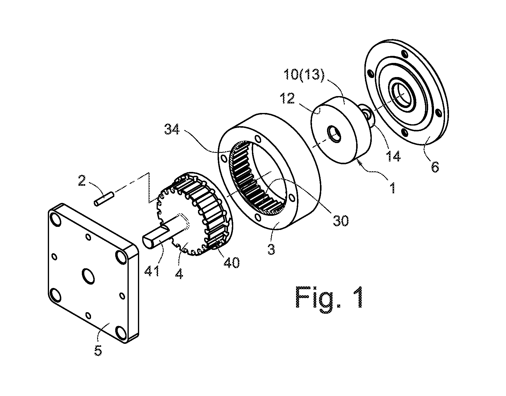
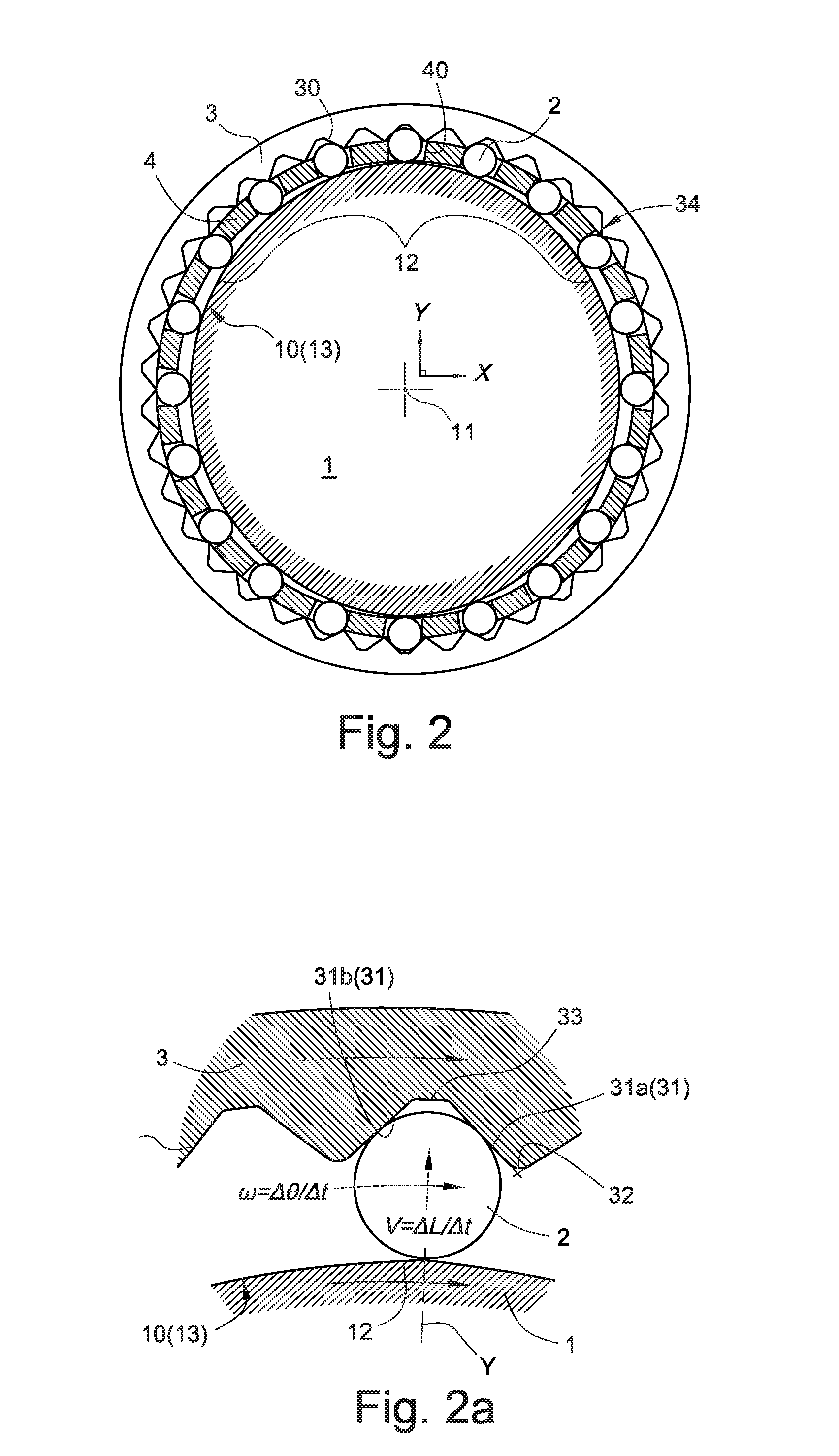
[0042]Please refer to FIGS. 1 and 2 which respectively demonstrate the members and the arrangement of the roller-type wave-motion designed in the present invention. A cam 1, a plurality of rollers 2, a bearing member 4 and a spline wheel 3 are arranged co-axially from outside to inside between a seat 5 and a cover 6 in the wave-type wave-motion. An input shaft 14 is disposed at the axial position of the cam 1 to be used as an input end of the torque of the wave-type wave-motion. The input shaft 14 can be transmitted rotational energy to input and drive the cam 1 to rotate. A convex arc 12 in spline line shape and relatively far from the axis 11 is disposed a cam surface 10 of the cam 1. The convex arc 12 is used as an effective functional area for pushing and driving the roller to transmit power. A cam periphery 13 is formed on the cam 1. In a preferred embodiment of the invention, the roller 2 is in cylinder shape. But, the roller 2 might be a bearing bead used as a roller part. Th...


PUM


Abstract

A method for designing a spline surface contour of a roller-type wave-motion includes of the steps of slicing radial movement track of a roller between a cam and a spline aperture and circumference rotation track at equal proportion at equal time intervals to sequentially obtain circle centers and points of tangency of the track circles during movement of the roller; connecting the points of tangency to form a unit cam circumference segment of a cam periphery in order to draw and form a single-sided tooth flank contour; and forming a correspondent side tooth flank contour by mirroring and projecting the single-sided tooth flank contour. A method of forming a spline wheel contour and a method of forming a cam periphery are obtained.

Description

BACKGROUND OF THE INVENTION[0001]1. Field of the Invention[0002]The present invention relates to a method of designing a member of roller-type wave-motion, particularly to a method of designing a spline wheel contour, a spline surface contour and a cam periphery of a roller-type wave-motion.[0003]2. Description of Related Art[0004]In the conventional techniques, there are no wave-motions involved. A similar wave-motion of the prior arts is spin-wave driver for generating sine or cosine transmission waveforms.[0005]Conventional spin-wave drivers and planetary gears belong to typical speed reduction gearing devices. A spin-wave driver is a speed reduction gearing device. The first spin-wave driver invented is a Harmonic® driver disclosed in U.S. Pat. No. 2,906,143 filed in 1955 by C. W. Musser. After continuous improvement, details of a spin-wave driver mechanism are disclosed in U.S. Pat. No. 5,643,128. In comparison to conventional planetary gears, conventional spin-wave drivers cou...

Claims


Application Information

Patent Timeline
IPC IPC(8): F16H49/00
CPCF16H49/001F16H25/00F16H55/00
Inventor LIANG, CHIA-SHENGCHENG, HUNG-TAIHUANG, SZU-MING
Owner PRODRIVES & MOTIONS
Why Eureka
Try Eureka