
Helicon yield plasma electromagnetic ram-scramjet drive rocket ion vector engine

Inactive Publication Date: 2016-12-29
SONIC BLUE AEROSPACE
View PDF8 Cites 13 Cited by
  • Summary
  • Abstract
  • Description
  • Claims
  • Application Information

AI Technical Summary

Benefits of technology

The patent describes a new propulsion system for hypersonic space flight that combines a common flow path with different engine cycles to improve performance. The system includes a superconducting tunnel for acceleration, a ram-scramjet for combined subsonic and supersonic compression, and an ionized plasma drive for high-speed flight. The system can achieve high thrust and sustain for space flight, with a broad Mach number range from static conditions to extreme altitudes. The technical effects of the system include improved propulsion efficiency, increased specific impulse power, and reduced eddy currents.

Problems solved by technology

These gas turbine machine propulsion engines require the considerable oxygen content up to altitudes of 50,000 feet to operate effectively burning kerosene based hydrocarbon fuels, but are limited to relatively low speeds of Mach 0.85.
Beyond these speeds it is difficult for these engine designs with mechanical rotating compressor machinery to compress air at faster speeds and still sustain combustion along with the potential deleterious effects of aerothermodynamic drag.
Airflow is moving so last that residence time to achieve combustion, on the order of micro seconds, has been problematic for decades for scramjet designers.
Subsequently, to attenuate flow speeds in the combustor, cavity design to produce non-laminar flow and swirl has been introduced in scramjet designs, but to the negative effect that inlet-unstart becomes prevalent (the engine stalls).
This is basically an enormous waste of energy as the number of pounds of propellant to generate a pound of thrust is vastly inefficient with the problem being compounded by a vertical take-off launch vehicle, such as the space shuttle.

Method used


Image

  • Helicon yield plasma electromagnetic ram-scramjet drive rocket ion vector engine
  • Helicon yield plasma electromagnetic ram-scramjet drive rocket ion vector engine
  • Helicon yield plasma electromagnetic ram-scramjet drive rocket ion vector engine

Examples


Embodiment Construction

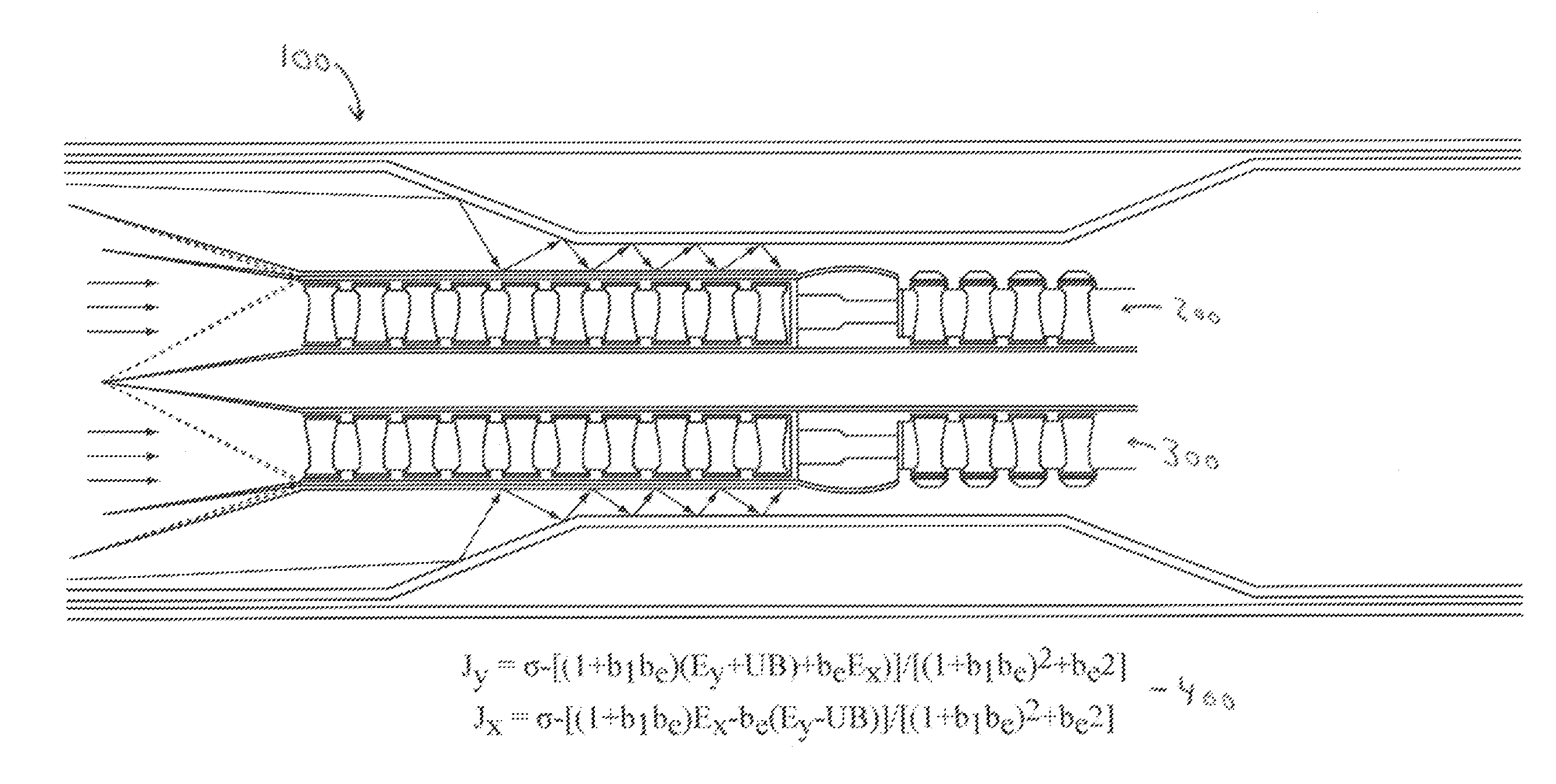
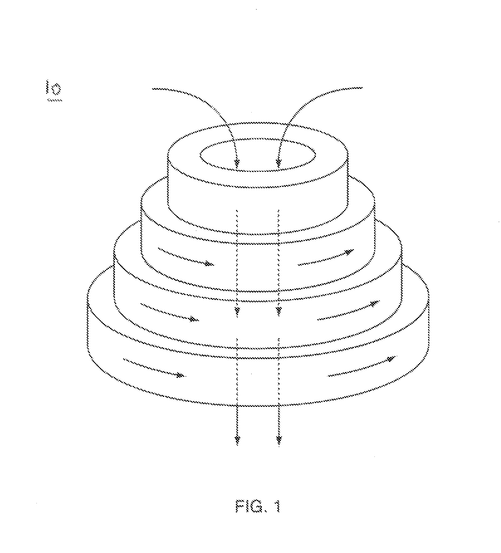
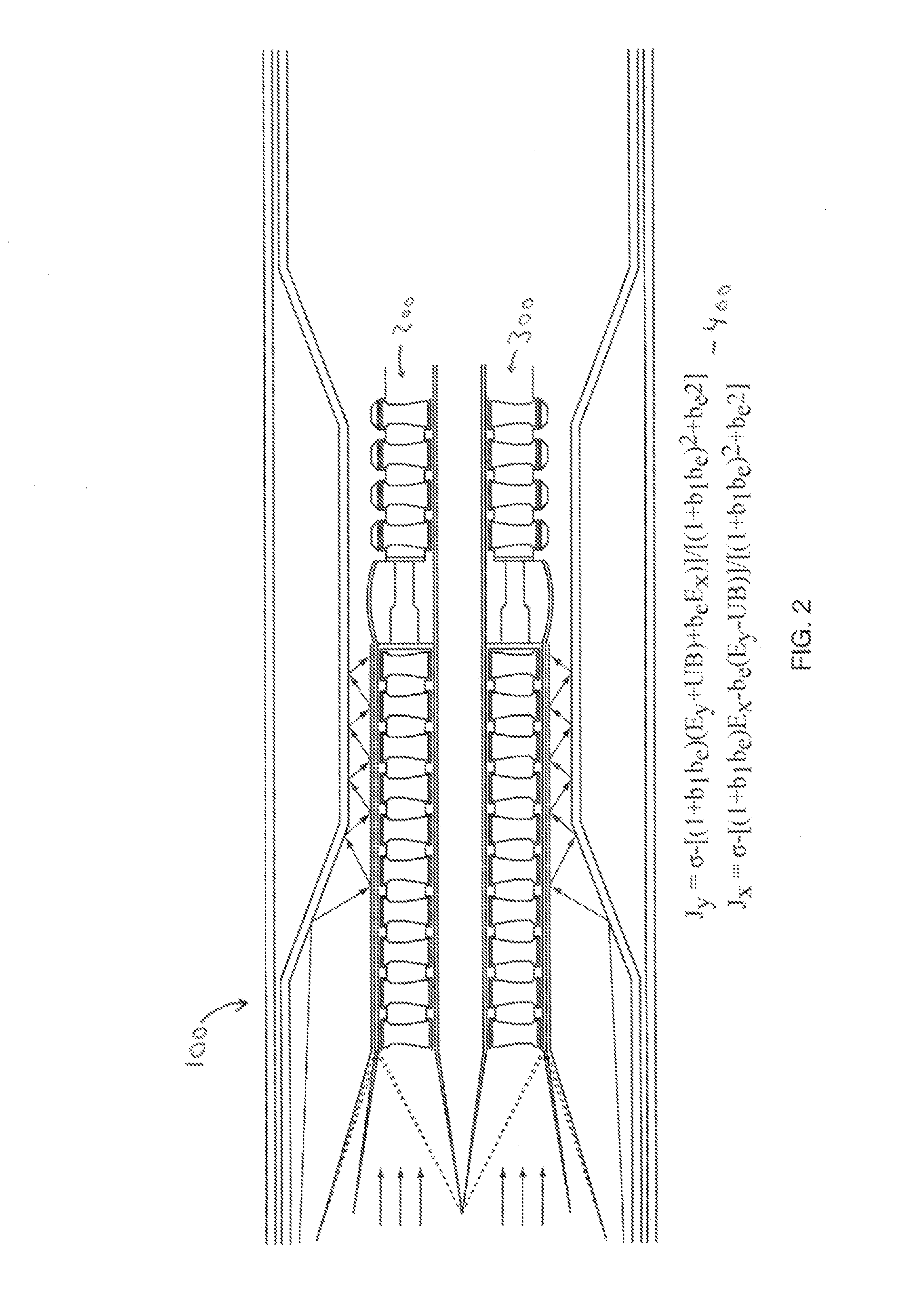
[0026]Real progress in understanding and the control of hypersonic flows and hypersonic air breathing engines, combined with a superconducting axial and Normal vector flow field at the HYPERDRIVE core (combustor location) at sufficient magnetic flux density and ionization power, eventually rests upon the derivation of novel and unique analytical methods, and mathematical modeling so as to forecast predict, and compute their behavior. The combining of the ram-scramjet dual mode use combustor technology, and high “Tesla” field rotating Normal (vector) and axial magnetic flow fields to power and catalyze combustion across multi-phase combustion, Mach number flight conditions, has not been done before, and is novel and unique. The following mathematical equation analysis is the objective study of such a multi-Mach number, multi-engine cycle hypersonic space scramjet called HYPERDRIVE. The essential core innovation in HYPERDRIVE is the superconducting powershaft core SPSC fully integrate...


PUM


Abstract

HYPERDRIVE receives continuous air breathing assistance from compressed atmospheric air through a high speed magnetically core driven turbine accelerator which resolves around a common flow path tunnel. The tunnel runs from the front to the back of the engine. It is assisted by a series of radial geometric ramjet engines that share the common flow path tunnel for hypersonic exhaust but has separate inlet air from a linear aerospike which governs mass flow of air, velocity of inlet air and pressure to the turbine and / or ramjets, as well as the positioning of the shock wave at the inlet to reduce aerodynamic drag. The ramjet is of hybrid engine design where it can also function as a scramjet, thus a ram-scramjet structure for combustion in a radial configuration about the engine (aft of an electrical compressor), where the common flow path tunnel also serves as a compression tunnel to compress air through a the constantly occurring series of compression shocks entering from and around the aerospike.

Description

CROSS REFERENCE TO RELATED APPLICATION[0001]This application is a nonprovisional and claims the priority benefit of U.S. provisional patent application Ser. No. 61 / 800,408 filed Mar. 15, 2013, of the same investor. The content of that application is incorporated herein by reference.FIELD OF THE INVENTION[0002]The engine described herein relates generally to ion plasma engines, ramjet engines, scram jet engines, turbine engines, and ion plasma helicon drive engines, derivatives thereof, their operating modes, and the distinction in the invention, of those practiced in the art, to the novelty and uniqueness of a particular hybrid space engine design, in of the invention, that incorporates all four types of engine cycles.BACKGROUND OF THE INVENTION[0003]Even before the first Lunar landing on the moon propulsion experts and scientists were studying the benefits of single stage to orbit combined cycle air breather and rocket based propulsion systems for horizontal take off launch vehicle...

Claims


Application Information

Patent Timeline
IPC IPC(8): F02K7/16F02K5/00H02K44/04F03H1/00
CPCF02K7/16F03H1/00F02K5/00F05D2220/80F05D2200/00F05D2220/10F05D2220/323H02K44/04H02K44/00F02C3/20
Inventor LUGG, RICHARD H.
Owner SONIC BLUE AEROSPACE
Learn More