
Semi-floating gate fet

a floating gate and gate technology, applied in the direction of semiconductor devices, electrical equipment, transistors, etc., can solve the problems of increasing the footprint of the device, limiting the memory density of the sfg transistor array, and catching the charge placed on the floating ga

Active Publication Date: 2016-12-15
STMICROELECTRONICS SRL
View PDF4 Cites 34 Cited by
  • Summary
  • Abstract
  • Description
  • Claims
  • Application Information

AI Technical Summary

Benefits of technology

The vertical SFG FET is a new type of semiconductor device that includes a vertical TFET and a vertical p-n diode. This device can be used in low-power, low-voltage applications, making it ideal for improving memory density and speed while reducing power consumption. The vertical SFG FET is compatible with existing CMOS manufacturing processes, making it easy to fabricate. Overall, the vertical SFG FET provides better performance and higher efficiency compared to conventional planar devices.

Problems solved by technology

The floating gate is thus electrically isolated, so that charge placed onto the floating gate is trapped.
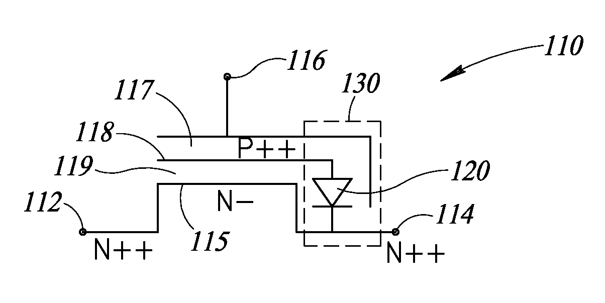
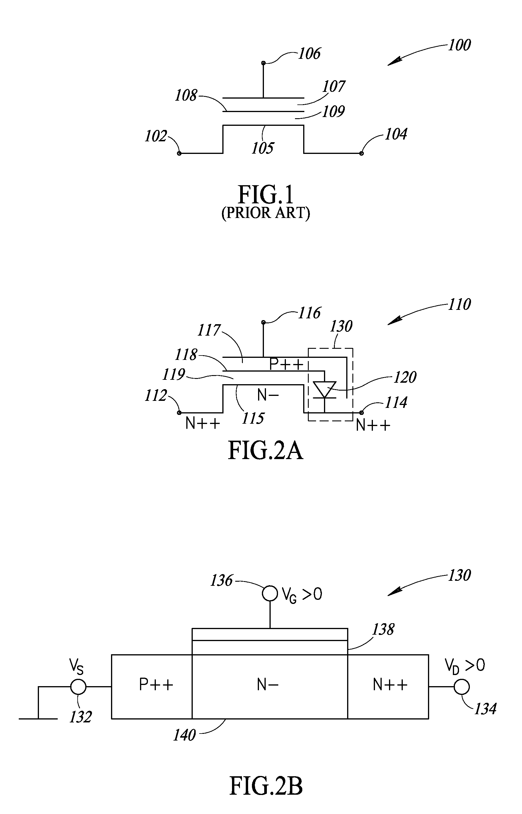
However, a disadvantage of the SFG transistor shown in FIGS. 2a and 2b is that the extensions made to form the p-n diode and the TFET increase the footprint of the device, which limits the memory density of a SFG transistor array.

Method used


Image

  • Semi-floating gate fet
  • Semi-floating gate fet
  • Semi-floating gate fet

Examples


Embodiment Construction

[0031]In the following description, certain specific details are set forth in order to provide a thorough understanding of various aspects of the disclosed subject matter. However, the disclosed subject matter may be practiced without these specific details. In some instances, well-known structures and methods of semiconductor processing comprising embodiments of the subject matter disclosed herein have not been described in detail to avoid obscuring the descriptions of other aspects of the present disclosure.

[0032]Unless the context requires otherwise, throughout the specification and claims that follow, the word “comprise” and variations thereof, such as “comprises” and “comprising” are to be construed in an open, inclusive sense, that is, as “including, but not limited to.”

[0033]Reference throughout the specification to “one embodiment” or “an embodiment” means that a particular feature, structure, or characteristic described in connection with the embodiment is included in at le...


PUM


Abstract

A semi-floating gate transistor is implemented as a vertical FET built on a silicon substrate, wherein the source, drain, and channel are vertically aligned, on top of one another. Current flow between the source and the drain is influenced by a control gate and a semi-floating gate. Front side contacts can be made to each one of the source, drain, and control gate terminals of the vertical semi-floating gate transistor. The vertical semi-floating gate FET further includes a vertical tunneling FET and a vertical diode. Fabrication of the vertical semi-floating gate FET is compatible with conventional CMOS manufacturing processes, including a replacement metal gate process. Low-power operation allows the vertical semi-floating gate FET to provide a high current density compared with conventional planar devices.

Description

BACKGROUND[0001]Technical Field[0002]The present disclosure generally relates to semi-floating gate devices for use in semiconductor memory applications.[0003]Description of the Related Art[0004]A FinFET is an electronic switching device in which a conventional planar semiconducting channel is replaced by a semiconducting fin that extends outward from a top surface of a silicon substrate. In such a device, the gate, which controls current flow in the fin, wraps around three sides of the fin so as to influence current flow from three surfaces instead of one. The improved control achieved with a FinFET design results in faster switching performance and reduced current leakage than is possible with a planar transistor. FinFETs are described in further detail in U.S. Pat. No. 8,759,874, and U.S. Patent Application Publication US2014 / 0175554, assigned to the same assignee as the present patent document.[0005]A vertical GAA FET is a linear, or 1-D, device in the form of a nanowire, orient...

Claims


Application Information

Patent Timeline
IPC IPC(8): H01L29/788H01L27/088H01L29/66
CPCH01L29/7883H01L27/088H01L29/66825H01L29/66666H01L29/7889
Inventor LIU, QINGZHANG, JOHN H.
Owner STMICROELECTRONICS SRL
Learn More