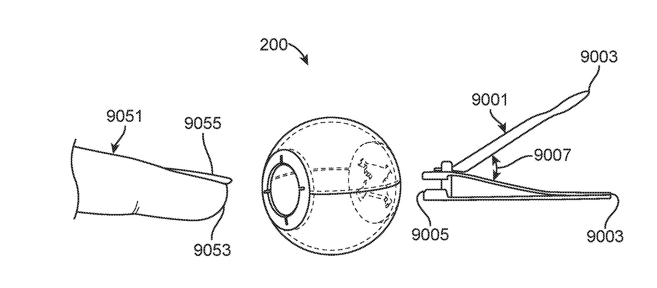
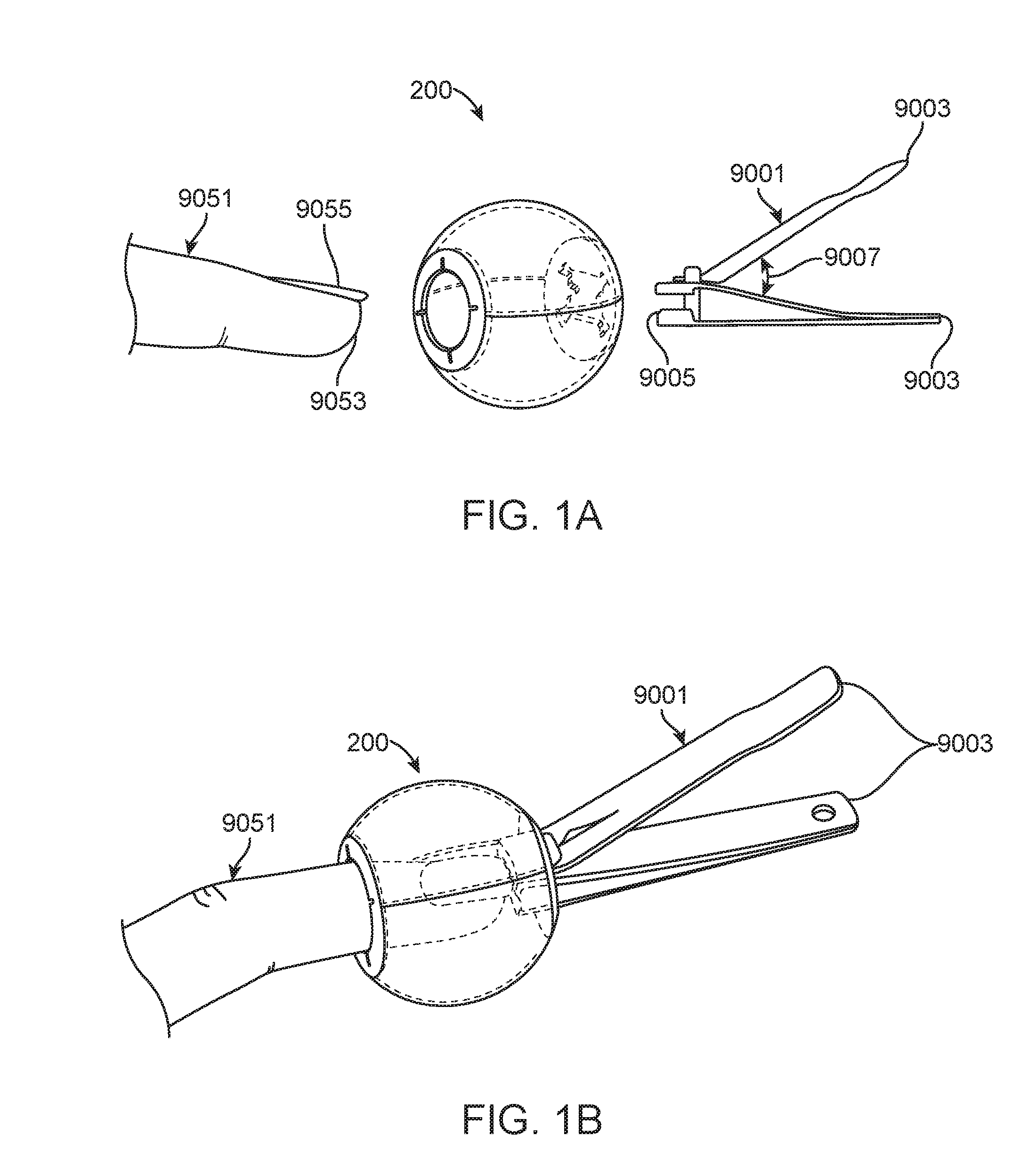
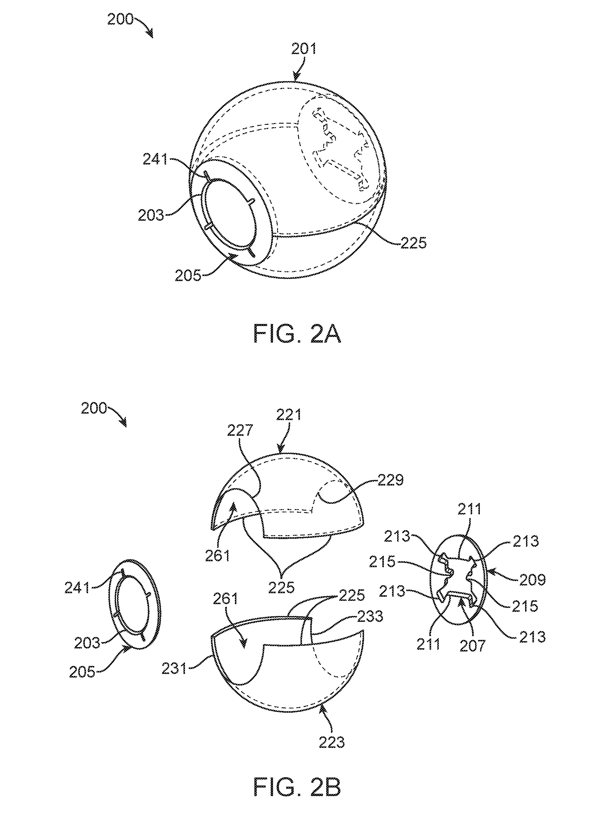
Unless some accessory device is used, typically when nails (e.g., fingernails and / or toenails) are clipped (e.g.,
cut or trimmed) by use of a
nail clipper, the nail clippings launch and / or fall in a
chaotic and generally unpredictable manner, that may result in unfound nail clippings remaining in an environment, and even after cleanup efforts.
Such nail clipping efforts also generate the added and extra step of having to search and
clean up the
cutting environment.
Such nail clipping efforts are also unsanitary, as nail clippings may often harbor undesirable
bacteria and fungal organisms.
Such nail clipping efforts may also be dangerous, in that some nail clippings may be sharp and may
pose a puncture risk to unprotected
skin regions that accidently stumble upon loose nail clippings.
And due at least in part to the foregoing, many people find loose nail clippings unpleasant and would rather not have to encounter such loose nail clippings.
However, a problem with such art is that cut nail clippings do not always necessarily fall or launch towards such a reservoir region in the modified
handle, i.e., such art may not capture nail clippings that fall or launch in other directions.
Additionally, cleaning, sanitizing, and / or sterilizing such devices may be difficult to impossible, due to materials of construction, excessively complex
surface geometry, and / or hard to reach regions.
The two opposing openings to the
enclosure's interior do not teach any unique structures / geometry that helps to removably mate / seal with the inserted article (e.g., a digit or a nail clipper) being inserted into the given hole, and this provides regions where cut nail clippings may escape the device.
This VELCRO within the
enclosure poses two problems.
First, this creates a region that is likely to retain cut nail clippings, including nail dust, and thus poses a
contamination risk.
Second, minimizing movement of the nail clipper within the
enclosure is added undesirable complexity to the device and is unnecessary if the overall device enclosure and its openings are sized properly.
Additionally, there are no explicit teachings for any structures, geometries, or features that would facilitate cleaning,
sanitation, and / or sterilization of the device.
Whether this flexible
grommet structure is used to seal around an inserted digit or an inserted nail clipper, this flexible
grommet is problematic as it provides excessive “nooks and crannies” (i.e.,
surface geometry in close proximity to other
surface geometry that may be close enough to trap nail dust and cut nail clippings) that may be readily contaminated and colonized by
bacteria and fungi common to nails.
This arrangement is undesirable as it adds unnecessary complexity because now, instead of inserting the nail clipper into one opening, the nail clipper must be inserted into two openings.
Some embodiments of Morelli are also undesirably bulky or cumbersome.
Some embodiments of Morelli accept more than one digit into the enclosure at a given time, which may unnecessarily
expose too much
skin to bacterial and / or
fungal contamination.
Additionally, there is no explicit teachings for any structures, geometries, or features that would facilitate cleaning,
sanitation, and / or sterilization of the enclosure devices.
Addition of this elongated
rigid rod 56 is undesirable and its inclusion is unnecessary and simply adds complexity to the overall device.
Additionally, inclusion of this rod also makes cleaning, sanitizing, and / or sterilizing interior surfaces of the sphere more difficult and challenging.
Additionally, the two opposing openings to the sphere's interior do not teach any unique structures / geometry that help to removably mate with the inserted article (e.g., a digit or a nail clipper) being inserted into the given hole and this provides regions where cut nail clippings may escape the device.
This device suffers from several problems.
Second, the device is too flexible, i.e., excessively flexible with no supporting structure, and this makes using the device more difficult than it should be as extra steps are needed to arrive at correct positioning to cut nails and to see what one is doing.
However, these devices suffer from being too cumbersome and too bulky.
Additionally, there are cleaning, sanitizing, and / or sterilization problems.
Separating the nail clippers from such devices may entail extra steps and extra effort and may be difficult, which may be important as nail clippers are often constructed from different materials (e.g., metals) than the catching device, which may create problems for cleaning, sanitizing, and / or sterilization as different types of materials may utilize different methods of cleaning, sanitizing, and / or sterilization.
For example, microwaving the metallic nail clippers would be problematic, which necessitates removal of such nail clippers from the catching device when
microwave sterilization may be employed.
This product also suffers from a number of problems.
First, the product only has one top located window, located in an otherwise top opaque surface and all other major surrounding surfaces of the container are also opaque, which results in a
working space of inside the container being relatively dark, which has resulted in the product including a LED
light source, which adds complexity, weight, and cost to the overall product.
Such presence of
electronics complicates cleaning, sanitizing, and / or sterilizing options.
Additionally, end caps of the container, which house the digit opening and a nail clipper opening may be removed, and upon removal, this reveals complicated geometry, such as tabs with holes and a rail
system to accept the top surface, wherein the tabs with holes and the rails provided complicated geometry for allowing nail clippings and nail dust to get stuck and / or accumulate and thus provide additional surfaces areas, that are difficult to clean, for buildup of undesirable
microbial contamination.
Additionally, because of the closeness of such closely spaced membranes, cleaning, sanitizing, and / or sterilizing this region is unnecessarily difficult.
None of the above noted prior art teaches a nail clippings catcher device that comprises a clipper hole with a unique geometry that is both easy to use and still mitigates against escape of cut nail clippings from the given nail clippings catcher device.
Additionally, none of the above noted prior art were designed specifically to ease cleaning,
sanitation, and / or sterilization of the given nail clippings catcher device.


