Sight-line detection method and device, and three-dimensional view-point measurement device
a detection method and a three-dimensional viewpoint technology, applied in the field of sightline detection methods and devices, and three-dimensional viewpoint measurement devices, can solve the problems of limited measuring range, huge load on the subject, and impede the everyday behavior of the subj
- Summary
- Abstract
- Description
- Claims
- Application Information
AI Technical Summary
Benefits of technology
Problems solved by technology
Method used
Image
Examples
embodiment 1
[0215]As shown in FIG. 9, two cameras (camera 101, camera 102) are placed apart from a face 107 of a subject and light sources 105 and 106 of the same wavelength are provided substantially inside an aperture or near the aperture of lenses 103 and 104 of these cameras to illuminate the whole face 107. The two cameras (camera 101, camera 102) are driven synchronously to turn on the light sources 105 and 106 mounted on the two cameras alternately in sync with an odd field and an even field.
[0216]As shown in FIG. 10, when the light source 105 mounted on the one camera 101 is turned on in the odd field, a phenomenon in which pupils are taken brighter than surroundings in images of the odd field of the one camera 101 occurs (bright pupil: FIG. 11 (left)), and another phenomenon in which pupil images are taken darker than surroundings in images of the odd field of the other camera 102 occurs (dark pupil: FIG. 11 (right)).
[0217]Similarly, when the light source 106 mounted on the other camer...
embodiment 2
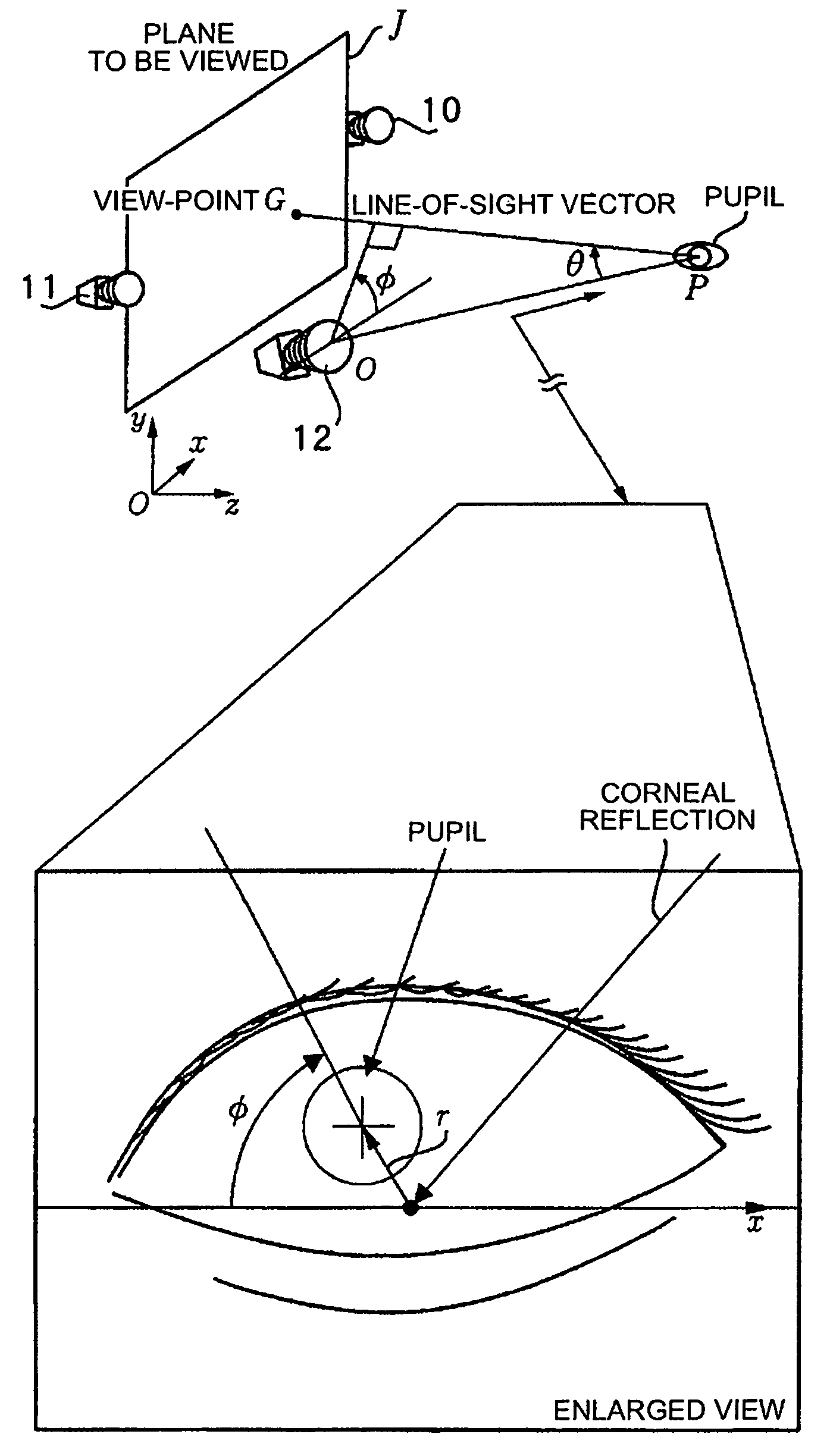
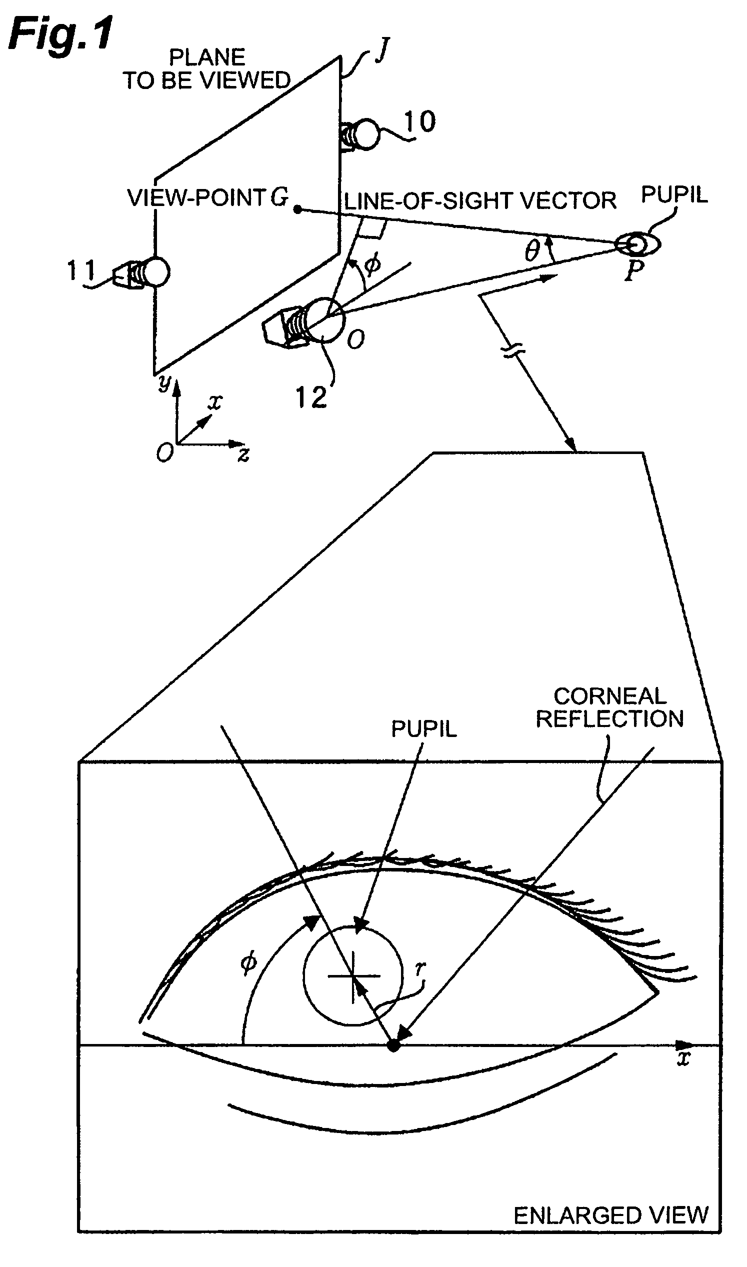
[0224]Each of the two cameras can basically detect the line-of-sights of both eyes. Now, as shown in FIG. 15, for the line-of-sight of one eye, three-dimensional coordinate of the pupil in the world coordinate system constructed when camera calibration of two cameras is performed is estimated from pupil coordinate obtained from the two cameras. Now, only the camera on the left is noticed. A camera-pupil vector in the world coordinate system is determined from three-dimensional coordinate of the pupil estimated and coordinate of the camera determined by camera calibration. If the line-of-sight vector is defined as a vector directed from the pupil to the view-point, the angle formed by the camera-pupil vector and the line-of-sight vector can be represented by θ and φ in the diagram, where θ is, in the range of about ±30 degrees, approximately linearly related to |r| of a vector r directed from the corneal reflection center to the pupil center in the image shown in FIG. 16 (θ=k|r|, whe...
embodiment 3
[0241]With capabilities of simultaneously measuring the line-of-sights of both eyes, it becomes possible to measure an angle of convergence (angle formed by the line-of-sights of both eyes) and a view-point in the depth direction (intersection of the line-of-sights of both eyes), indicating the distance to an object being gazed at. As a result, the view-point in three-dimensional space can be known.
[0242]This suggests an application to evolved 3D display and the like. If the eyes are not focused on a normal 3D display, it is not possible to view clear images. Thus, a watcher is forced to watch in an unnatural way against the normal human visual function that the eye focus does not change when the angle of convergence changes. However, by using an evolved 3D display that, even if the focus is shifted in the depth direction, comes into focus accordingly, more natural three-dimensional visual appreciation will be experienced.
[0243]In this type of display, by providing spatial positions...
PUM
 Abstract
Description
Claims
Application Information
 - R&D
- Intellectual Property
- Life Sciences
- Materials
- Tech Scout
- Unparalleled Data Quality
- Higher Quality Content
- 60% Fewer Hallucinations
Browse by: Latest US Patents, China's latest patents, Technical Efficacy Thesaurus, Application Domain, Technology Topic, Popular Technical Reports.
© 2025 PatSnap. All rights reserved.Legal|Privacy policy|Modern Slavery Act Transparency Statement|Sitemap|About US| Contact US: help@patsnap.com


