
Method for formation of iron sprayed coating and coated member

a technology of coating and coating, applied in the direction of coatings, mechanical equipment, machines/engines, etc., can solve the problems of reducing the adhesion strength between the sprayed coating and the substrate, reducing the machinability of the sprayed coating, etc., to improve the adhesion, improve the scuffing resistance and wear resistance, and improve the effect of machinability

Inactive Publication Date: 2016-08-18
TOYOTA JIDOSHA KK
View PDF2 Cites 1 Cited by
  • Summary
  • Abstract
  • Description
  • Claims
  • Application Information

AI Technical Summary

Benefits of technology

The patent describes using a low-carbon-containing steel wire for arc spraying to increase the viscosity of droplets and inert gas to increase surface tension, resulting in coarser droplets that are more stable. These droplets have increased heat and can adhere to the substrate better, leading to an improved adhesion strength of the iron sprayed coating.

Problems solved by technology

Although use of materials containing an increased amount of carbon as JP 2009-155720 A and JP 2010-275581 A may improve wear resistance of the sprayed coatings, it may also decrease machinability of the sprayed coatings.
However, the method of forming a coating disclosed in JP 2008-240029 A may result in a decreased adhesion strength between the sprayed coating and the substrate because spraying is carried out with air containing oxygen.

Method used


Image

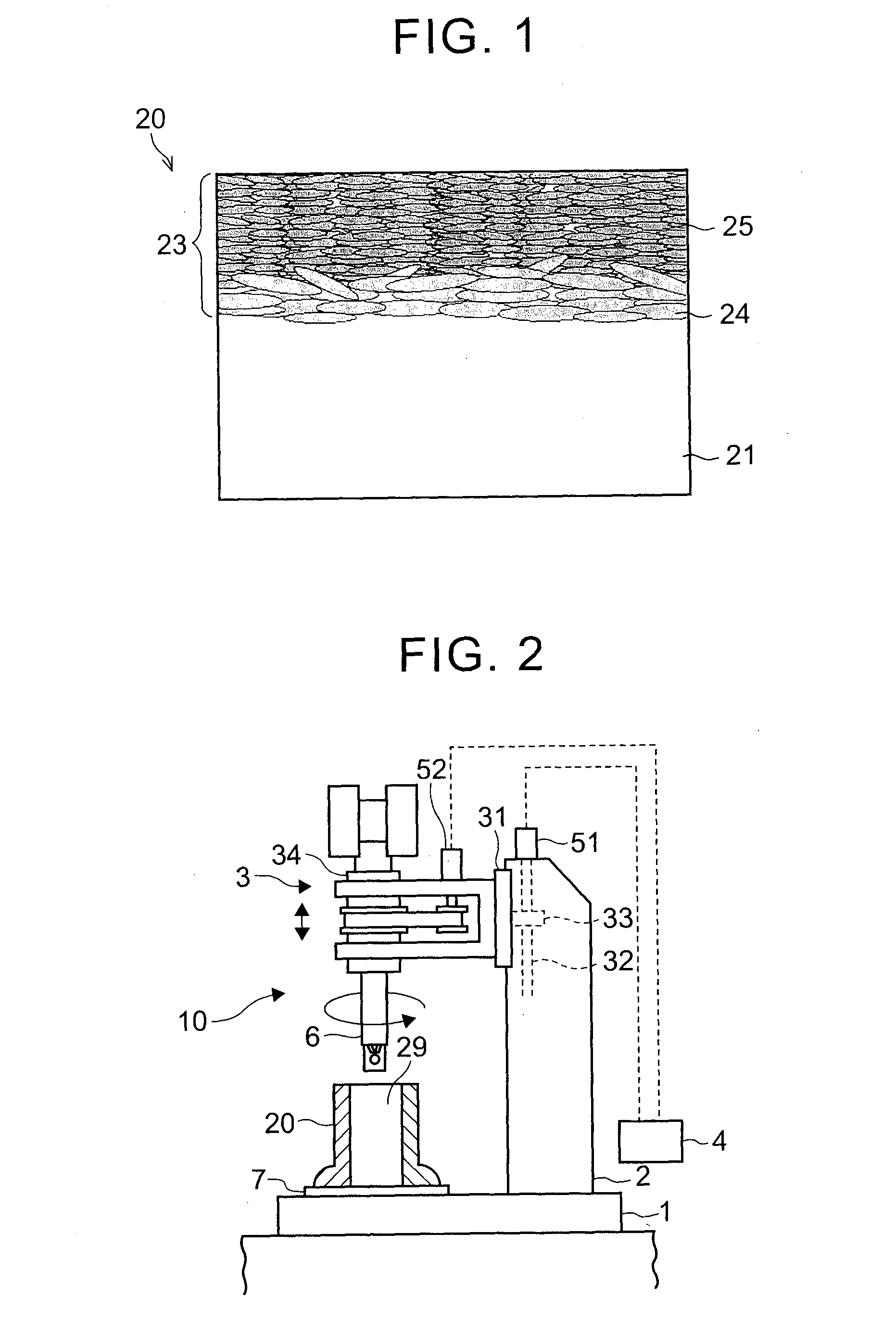
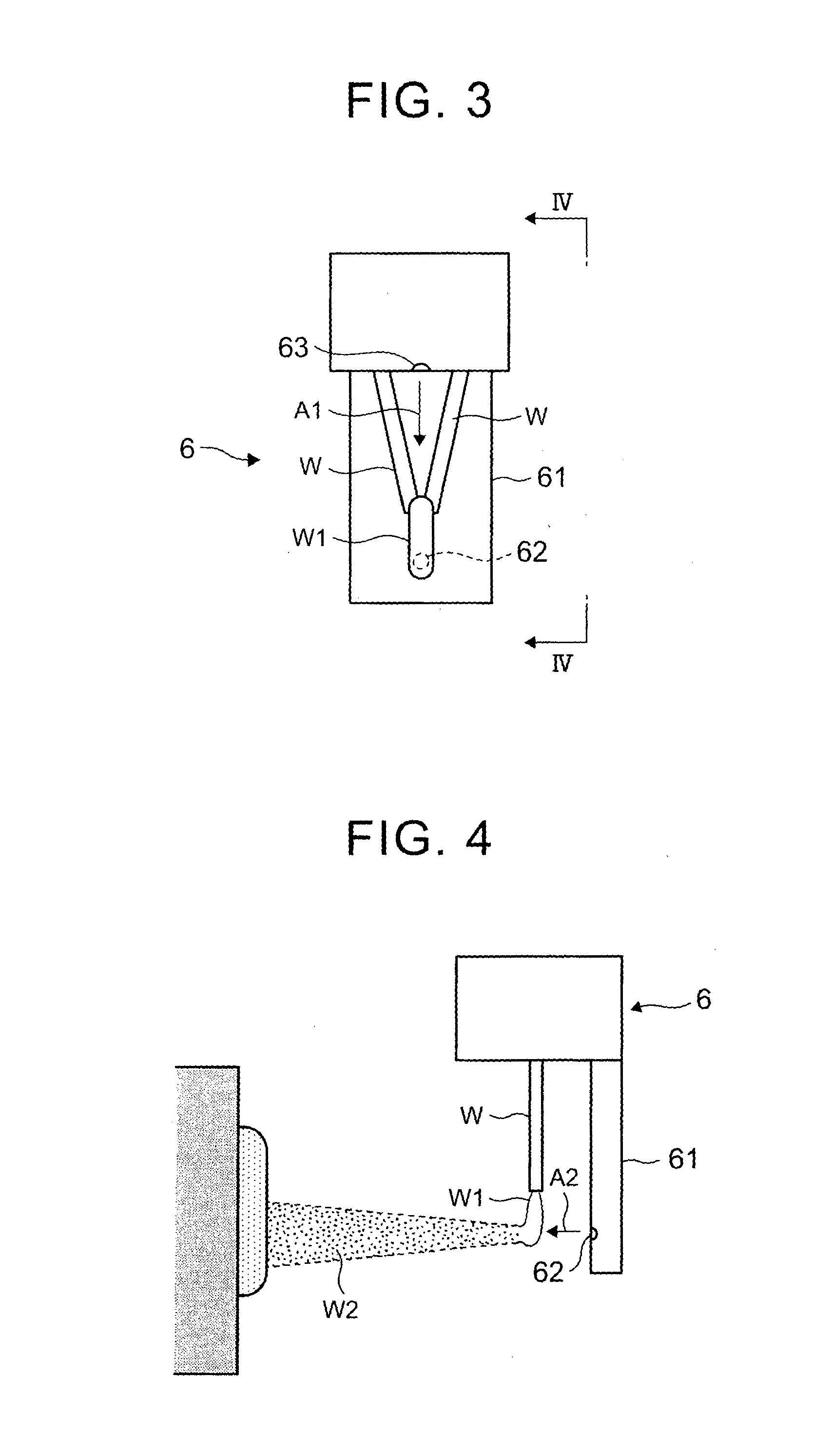
  • Method for formation of iron sprayed coating and coated member
  • Method for formation of iron sprayed coating and coated member
  • Method for formation of iron sprayed coating and coated member

Examples


example 1

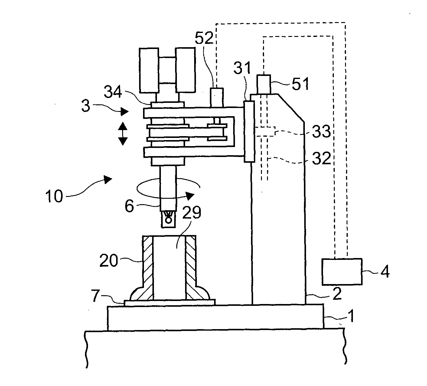
[0124]A member coated with an iron sprayed coating of Example 1 was prepared in the same manner as the coating A except that the first iron sprayed coating which was the iron sprayed coating of the coating A was formed with the moving speed of 16 mm / sec and then an iron sprayed coating was similarly formed using a gas supply device shown in FIG. 6 in order to supply oxygen gas-containing gas to the spraying device.

[0125]The conditions for formation of the second iron sprayed coating were: a wire supplying speed during spraying: 100 mm / sec; a wire diameter: φ 1.6 mm; applied voltage: 30 V and current: 280 A for electric arc; speed of descending / ascending of the spraying gun: 5.4 mm / sec; rotation speed of the spraying gun: 300 rpm; atomization gas flow rate 700 L / min; and compressed gas: nitrogen gas containing 10% by volume of oxygen. The iron sprayed coating of the sprayed coating-coated member was then subjected to cutting by boring and honing (rough finishing, semi-finishing and P...

example 2

[0126]A member coated with an iron sprayed coating of Example 2 was prepared as Example 1 except that the compressed gas used was nitrogen gas containing 21% by volume of oxygen.

example 3

[0132]Members coated with iron sprayed coatings of Example 3 were prepared in the same manner as Example 1 except that the atomization gas flow rate was 600 L / min, 700 L / min, 900 L / min, 1000 L / min or 1100 L / min. The iron sprayed coatings of the members coated with the iron sprayed coatings were subjected to the hardness test and the friction and wear test as the coating A was subjected those test, and moreover the coatings were also subjected to the scuffing resistance test (the time before generation of scuffing) in order to evaluate seizure resistance properties. The flying speed of the droplets depending on the atomization gas flow rate was measured with a Spray Watch from Osier. The iron sprayed coatings were observed by TEM and subjected to elemental analysis by EDX analysis. The results are shown in FIGS. 17 to 22.

[0133]FIG. 17 is a graph showing the correlation between the atomization gas flow rate during formation of the coatings according to Example 3 and the hardness of th...


PUM

PropertyMeasurementUnit
flying speedaaaaaaaaaa
crystal particle diameteraaaaaaaaaa
particle diameteraaaaaaaaaa

Abstract

A method for forming an iron sprayed coating on a substrate with droplets of a wire molten by an electric arc includes: a step of forming a first iron sprayed coating on the substrate, the wire for arc spraying being a first wire containing iron and 0.03 to 0.10% by mass of carbon and the compressed gas being inert gas; and a step of forming a second iron sprayed coating on the first iron sprayed coating, the wire for arc spraying being a second wire containing iron and 0.03 to 0.10% by mass of carbon and the compressed gas containing 10 to 21% by volume of oxygen gas.

Description

BACKGROUND OF THE INVENTION[0001]1. Field of the Invention[0002]The invention relates to a method for forming an iron sprayed coating formed with a wire for arc spraying by melting the wire for arc spraying by means of an electric arc and spraying the molten wire for arc spraying to a substrate while supplying compressed gas to the molten wire, and to a member with the iron sprayed coating which includes a substrate coated with the iron sprayed coating.[0003]2. Description of Related Art[0004]Internal surfaces of cylinder bores of cylinder blocks are coated with sprayed coatings formed by the spraying technique involving instantaneous melting of various metals or alloy metals by means of flames generated with an arc, plasma or gas and allowing collision / solidification and attachment of the sprayed particles atomized (rendered to be fine particles) by means of compressed gas, in order to improve corrosion resistance, wear resistance and the like of the internal surfaces of the bores....

Claims


Application Information

Patent Timeline
Patent Type & Authority Applications(United States)
IPC IPC(8): C23C4/131B32B15/01F02F1/00C23C4/06
CPCC23C4/02C23C4/08C23C4/131B32B15/011F02F1/004C22C38/02C22C38/04C23C4/06B32B15/012
Inventor MIYAMOTO, NORITAKAHIRANO, MASAKIKOZAKI, TOMOKO
Owner TOYOTA JIDOSHA KK
Learn More