Method of producing shaped steel changing in cross-sectional shape in longitudinal direction and roll forming apparatus for same

a technology of cross-sectional shape and rolling forming, which is applied in the field of method and roll forming for producing a shaped steel, can solve the problems of uneven springback due to high strength characteristics of steel materials, difficult to produce a hat-shaped steel as designed from such high tensile steel, and unsuitable roll forming, so as to prevent such interference, reduce the width of the cross-section, and eliminate the uneven springback

Active Publication Date: 2016-08-18
PEKING UNIV FOUNDER GRP CO LTD +3
View PDF1 Cites 2 Cited by
  • Summary
  • Abstract
  • Description
  • Claims
  • Application Information

AI Technical Summary

Benefits of technology

[0014]According to the present invention, by using a first rolling die having an annular ridge part which varies in cross-sectional shape in the circumferential direction and a second rolling die having an annular groove part which receives the annular ridge part of the first rolling die while maintaining a gap with the annular ridge part of the amount of thickness of the shaped steel, by simple control for making at least the first and second rolling dies rotate synchronized, a shaped steel with a cross-sectional shape which varies in the longitudinal direction can be produced. Accordingly, complicated control such as variable control of the roll widths of split rolls for broadening the width of the cross-section becomes unnecessary. Further, it is possible to realize the rolling forming apparatus of the present invention by changing the rolls of existing roll forming apparatuses to the first and second rolling dies.
[0015]Further, when using a first rolling die having an annular ridge part which varies in cross-sectional shape in the circumferential direction and a second rolling die having an annular groove part which receives the annular ridge part of the first rolling die while maintaining a gap with the annular ridge part of the amount of thickness of the shaped steel, sometimes interference will occur between the rolling dies. According to the present invention, it is possible to prevent such interference by providing relief which varies in relief amount in accordance with a relative angle with a rotation direction of the rolling dies.
[0016]In addition, by using the first and second rolling dies which have the above-mentioned roll barrel parts, even if the cross-sectional shape varies in the longitudinal direction, shaping is possible in the state with a constant gap between the two rolling dies, and therefore it is possible to eliminate the uneven occurrence of springback in the longitudinal direction, for example, due to an uneven gap, and possible to suppress buckling of the flange parts.

Problems solved by technology

For this reason, on the production floor of shaped steels, the problem of the springback due to the high strength characteristics of steel materials has been surfacing.
With general press forming, it is difficult to produce a hat-shaped steel as designed from such high tensile steel.
On the other hand, roll forming, unlike press forming (drawing), is not suited for forming a shaped steel which varies in cross-sectional shape in the longitudinal direction.
However, the roll forming process and apparatus disclosed in PLTs 1 to 3 have the problem of a complicated structure and method of control of the apparatus.
For this reason, it is difficult to convert existing facilities for use for working the inventions of PLTs 1 to 3.
Introduction of new facilities is necessary, and therefore the cost becomes high.
Further, if, as in the inventions of PLTs 1 and 3, broadening the roll widths of the split rolls during roll forming, there are the problems that only the corner parts at the front sides of the rolls will linearly contact the steel sheet material and, in high tensile steel or other materials, springback will occur unevenly in the longitudinal direction and the material will be distorted etc. in the longitudinal direction.

Method used


Image

  • Method of producing shaped steel changing in cross-sectional shape in longitudinal direction and roll forming apparatus for same
  • Method of producing shaped steel changing in cross-sectional shape in longitudinal direction and roll forming apparatus for same
  • Method of producing shaped steel changing in cross-sectional shape in longitudinal direction and roll forming apparatus for same

Examples


first embodiment

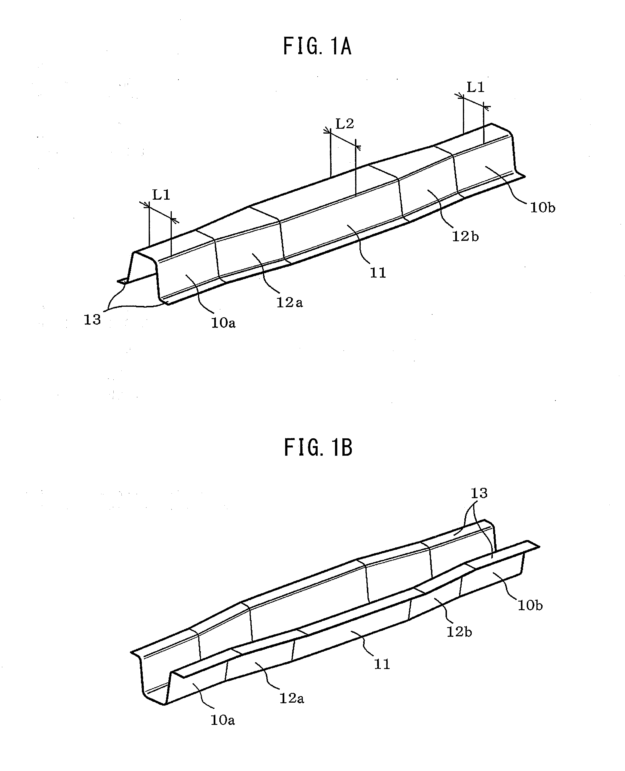
[0062]First, the shaped steel produced in the present embodiment will be explained. The shaped steel which is shown in FIGS. 1A and 1B is one example of a hat-shaped steel of a saddle shape which varies in cross-sectional shape in the longitudinal direction (for example, the metal stock axis direction). FIG. 1A is a perspective view of the hat-shaped steel seen from the upper side, while FIG. 1B is a perspective view seen from the lower side. The hat-shaped steel 1 comprises a top wall, side walls which extend along the two side edge parts of the top wall, and flanges which extend along the edge parts at the opposite sides of the side walls, and has a cross-section vertical to the longitudinal direction of the hat-shaped steel 1 (lateral cross-section) which is substantially hat shaped.

[0063]The hat-shaped steel 1 further has ̀‚portions 10a, 10b having top wall width of L1, a portion 11 having top wall width of L2 (>L1), and tapered transition portions 12a and 12b having expanding (o...

second embodiment

[0096]Next, a modification of the rolling dies which are shown in the above-mentioned first embodiment will be explained. In the rolling dies of the present embodiment, as shown in FIG. 8, the outside diameter of the annular ridge part 33 of the bottom roll 3 (hatched part) and the outside diameter of the bottom surface of the annular groove part 42 of the top roll 4 (hatched part) are the same, and the side walls of the annular ridge part 33 of the bottom roll 3 are provided with the later explained relief. Leaving aside this feature, the top and bottom rolls 4 and 3 of the present embodiment are substantially the same as the top and bottom rolls 4 and 3 of the first embodiment. Similar component elements are assigned the same reference notations, and detailed explanations are omitted.

[0097]The relief which is provided at the side surfaces of the annular ridge part 33 of the bottom roll 3 will be explained in detail. FIG. 9 is a partial vertical cross-sectional view which is cut al...

third embodiment

[0126]FIG. 23A shows a hat-shaped steel 1 with a constant width and height but with a cross-section which moves in the lateral direction, while FIG. 23B shows the top and bottom rolls 4 and 3 which form the hat-shaped steel 1 of FIG. 23A by the final forming operation. That is, in the above first embodiment, a hat-shaped steel with a straight stock axis was produced, but in the present embodiment, a hat-shaped steel 1 with a stock axis which is curved in the width direction is produced. This hat-shaped steel 1 has portions 15a of a straight stock axis and portions 15b of a curved stock axis. As the rolls for this, as shown by the example in FIG. 23B, top and bottom rolls 4 and 3 which have an annular ridge part and annular groove part offset in the rotational axial direction are used. The overall configuration of the roll unit which drives rotation of the top and bottom rolls 4 and 3 can be configured in the same way as in the first embodiment.

[0127]According to the present embodime...


PUM

PropertyMeasurementUnit
tensile strengthaaaaaaaaaa
tensile strengthsaaaaaaaaaa
radiusaaaaaaaaaa

Abstract

A roll forming apparatus for roll forming for producing from a sheet material a shaped steel which varies in cross-sectional shape in a longitudinal direction comprises a first rolling die which has an annular ridge part which varies in cross-sectional shape in a circumferential direction; a second rolling die which has an annular groove part which varies in cross-sectional shape in a circumferential direction; and a drive device for the first rolling die and the second rolling die. At least transition parts of the side surfaces of the annular ridge part of the first rolling die are provided with relief so that the gap with respect to the side surfaces of the annular groove part of the second rolling die becomes broader inward in the radial direction.

Description

TECHNICAL FIELD[0001]The present invention relates to a method and apparatus for roll forming for producing a shaped steel which varies in cross-sectional shape in the longitudinal direction.BACKGROUND ART[0002]As a method of producing a hat-shaped steel, which is one type of shaped steel, press forming using a punch and die is widely known. In bending into a hat shape by press forming, the problem of springback, that is, the sheet material trying to return to its original state due to the reaction force when the press pressure is removed, easily arises, and therefore in the past, countermeasures for suppressing springback have been studied.[0003]In this regard, in recent years, application of high tensile steel has been increasing. As one example, in the automobile industry, it is believed that reduction of the weight of the vehicle body will lead to reduction of the amount of emission of CO2 and therefore high tensile steel is being proactively used for the vehicle body material. ...

Claims


Application Information

Patent Timeline
Patent Type & Authority Applications(United States)
IPC IPC(8): B21D5/08
CPCB21D5/083
Inventor KUBO, MASAHIROYOSHIDA, HIROSHIMIZUMURA, MASAAKIDAIMARU, SEIICHI
Owner PEKING UNIV FOUNDER GRP CO LTD
Why Eureka
Try Eureka