
Multi-layered nanofiber medium using electro-blowing, melt-blowing or electrospinning, and method for manufacturing same

a nanofiber and nanofiber technology, applied in the field of multi-layered nanofiber filter media, can solve the problems of reducing the sustainability of the filter, affecting the performance of the filter, and being easily damaged by high temperature, and achieves the effect of reducing the cost of production

Inactive Publication Date: 2016-07-07
FINETEX ENE
View PDF4 Cites 20 Cited by
  • Summary
  • Abstract
  • Description
  • Claims
  • Application Information

AI Technical Summary

Benefits of technology

The production method of this patent is efficient and cost-effective. The resulting multi-layered nanofiber filter media has superior heat resistance, making it useful in applications requiring high-efficiency filters.

Problems solved by technology

Filter currently used in gas turbine has problems such as it is vulnerable to high temperature and foreign matter is not well eliminated.
Eventually, particles blocking gas hole of filter and fine particles increase pressure loss of a filter, decline sustainability of a filter, and with conventional filter medium there is difficulty in filtering fine pollutant particles having 1 micron or less nanosize.
In addition, as glass-fiber which is used as conventional heat-resistant filter material causes bad-influence to the environment, Europe and the United States are in the state of restricting glass-fiber use for environmental safety.
However, nonwoven fabric manufactured using such method has diameter of approximately 5˜500 μm range, and has difficulty in producing nanofiber 1 μm or less.
Therefore, filter comprising fiber with large diameter could filter large polluted particles, but filtering fine polluted particles of nanosize is virtually impossible.
However, the embodiment of nanofiber filter causes high production cost, as well as it is difficult to control various conditions for production, and therefore, filters using nanofiber cannot currently be supplied at comparatively low price.
In addition, conventional nanofiber-spinning technologies were limited to small-scale production mainly for laboratory and therefore did not have include concepts of division of spinning section into units or blocks, in which case nanofiber with one specific diameter was produced.
This resulted in limited air permeability and period of use.

Method used

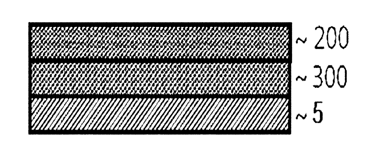
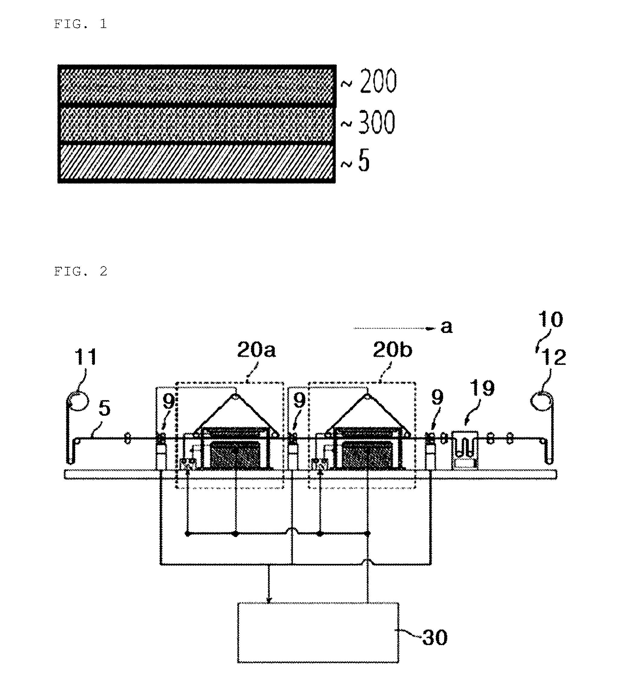
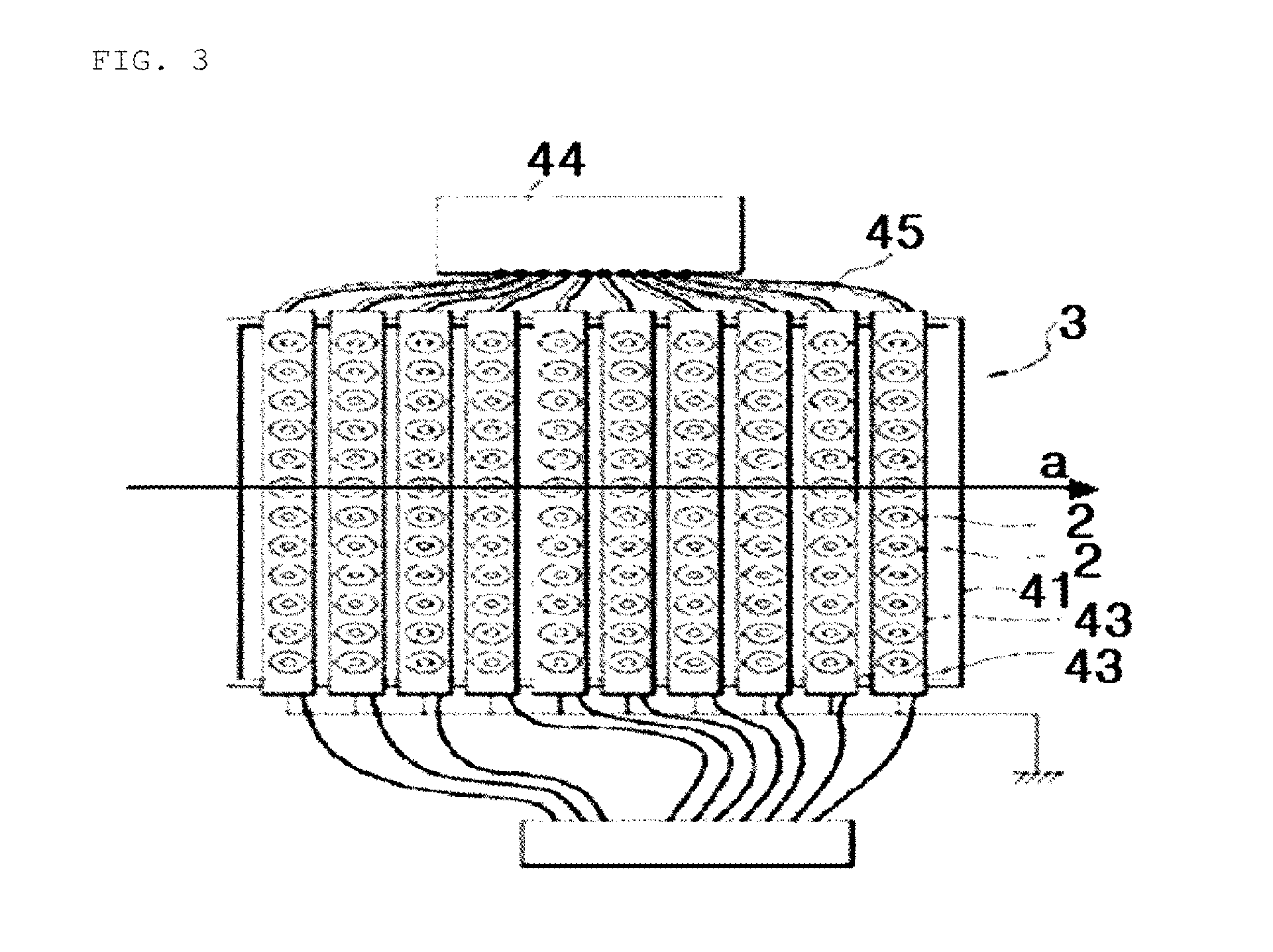

Image

  • Multi-layered nanofiber medium using electro-blowing, melt-blowing or electrospinning, and method for manufacturing same
  • Multi-layered nanofiber medium using electro-blowing, melt-blowing or electrospinning, and method for manufacturing same
  • Multi-layered nanofiber medium using electro-blowing, melt-blowing or electrospinning, and method for manufacturing same

Examples


example 1

Preparation of Multi-Layer Nanofiber Filter Media Using Electro Blown with Electro Electrospinning

[0181]Electro-blown and electro-spinning dope was prepared by dissolving polyacrylonitrile (Hanil Synthetic) of average weight molecular of 157,000 into dimethylformamide (DMF) in the first and the second phase. Under the condition where the distance between the electrode and the collector of the electro-blown and electro-spinning, respectively, is 40 cm, the applied voltage is 15 kV, the spinning liquid flow rate is 0.1 mL / h, the temperature is 22° C., and the humidity is 22%, we produced multi-layer nanofiber laminated on the cellulose substrate, by, on the cellulose substrate, forming polyacrylonitrile nanofiber whose thickness is 3 μm, and, during the second phase, by spinning polyacrylonitrile nanofiber, in the thickness of the same 3 μm, of the same polymer on the polyacrylonitrile on the surface of the substrate as the collector moves at a constant speed.

example 2

Preparation of Multi-Layer Nanofiber Filter Media Using Electro Blown with Electro Electrospinning

[0182]Electro-blown and electro-spinning dope was prepared by dissolving Polyamic Acid (PAA) of average weight molecular of 100,000 into the mixed solution (THF / DMAc) of Tetrahydrofuran (THF) and dimethylacetamide (DMAc) in the first and the second phase. Under the condition where the distance between the electrode and the collector of the electro-blown and electro-spinning, respectively, is 40 cm, the applied voltage is 15 kV, the spinning liquid flow rate is 0.1 mL / h, the temperature is 22° C., and the humidity is 22%, we produced multi-layer nanofiber laminated on the cellulose substrate, by, on the cellulose substrate, forming polyamic acid nanofiber whose thickness is 3 μm, and, during the second phase, by spinning polyamic acid nanofiber, in the thickness of the same 3 μm, of the same polymer on the polyamic acid nanofiber laminated on the surface of the substrate as the collector...

example 3

Preparation of Multi-Layer Nanofiber Filter Media Using Electro Blown with Electro Electrospinning

[0183]Electro-blown and electro-spinning dope was prepared by dissolving 100% nylon 6 monomer into the mixed solution of tetrafluoro acetic acid and dichloromethane (DCM) with the weight ratio of 5:5. Under the condition where the distance between the electrode and the collector of the electro-blown and electro-spinning, respectively, is 40 cm, the applied voltage is 15 kV, the spinning liquid flow rate is 0.1 mL / h, the temperature is 22′C, and the humidity is 22%, we produced multi-layer nanofiber laminated on the cellulose substrate, by, on the cellulose substrate, forming polyamide nanofiber whose thickness is 3 μm, and, during the second phase, by spinning polyamide nanofiber, in the thickness of the same 3 μm, of the same polymer on the polyamide on the surface of the substrate as the collector moves at a constant speed.


PUM

PropertyMeasurementUnit
Electrical resistanceaaaaaaaaaa
Heataaaaaaaaaa

Abstract

The present invention, aimed to enhance low heat-resistant ability of the current filters, relates to multi-layered nanofiber filter media and its manufacturing method, laminating nanofiber using electro-blown and electro-spinning subsequently on a cellulose substrate. In addition, the present invention relates to multi-layered nanofiber filter media and its manufacturing method, laminating nanofiber using melt-blown and electro-spinning subsequently on a cellulose substrate.

Description

TECHNICAL FIELD[0001]The present invention relates to a multi-layered nanofiber having increased heat resistance and its manufacturing method, using electro-blown or melt-blown, and electro-spinning. More particularly, it relates to the multi-layered nanofiber filter media and its manufacturing method by forming the first heat-resistant polymer nanofiber using electro-blown or melt-blown on a substrate, and by electro-spinning the second heat-resistant polymer on the above substrate, thereby having the second heat resistant polymer nanofiber laminated on the substrate.BACKGROUND ART[0002]Generally, a filter is a filtering medium which filters out foreign matter in fluid, and comprises a liquid filter and an air filter. An air filter is used for prevention of defective high-tech products along high-tech industry development. Installation in Clean room which completely eliminates biologically harmful things such as dust in air, particles, bio particles such as virus and mold, bacteria...

Claims


Application Information

Patent Timeline
IPC IPC(8): B01D39/16B29C70/02
CPCB01D39/163B29C70/026B29L2031/14B29K2077/00B29K2081/06B29K2033/20B01D39/18B01D2239/025B01D2239/0622B01D2239/0631B01D2239/0654B32B5/26B32B23/10B32B2262/0253B32B2262/0269B32B2262/0284B32B2307/306D04H1/4374D04H1/728
Inventor PARK, JONG-CHUL
Owner FINETEX ENE
Learn More