Coherent Diffractive Imaging With Arbitrary Angle of Incidence
a diffractive imaging and incidence angle technology, applied in the field of microscopy, can solve the problems of limiting the freedom of imaging geometry, low resolution of reconstructed images, and time-consuming methods, and achieve the effect of improving imaging prospects
- Summary
- Abstract
- Description
- Claims
- Application Information
AI Technical Summary
Benefits of technology
Problems solved by technology
Method used
Image
Examples
Embodiment Construction
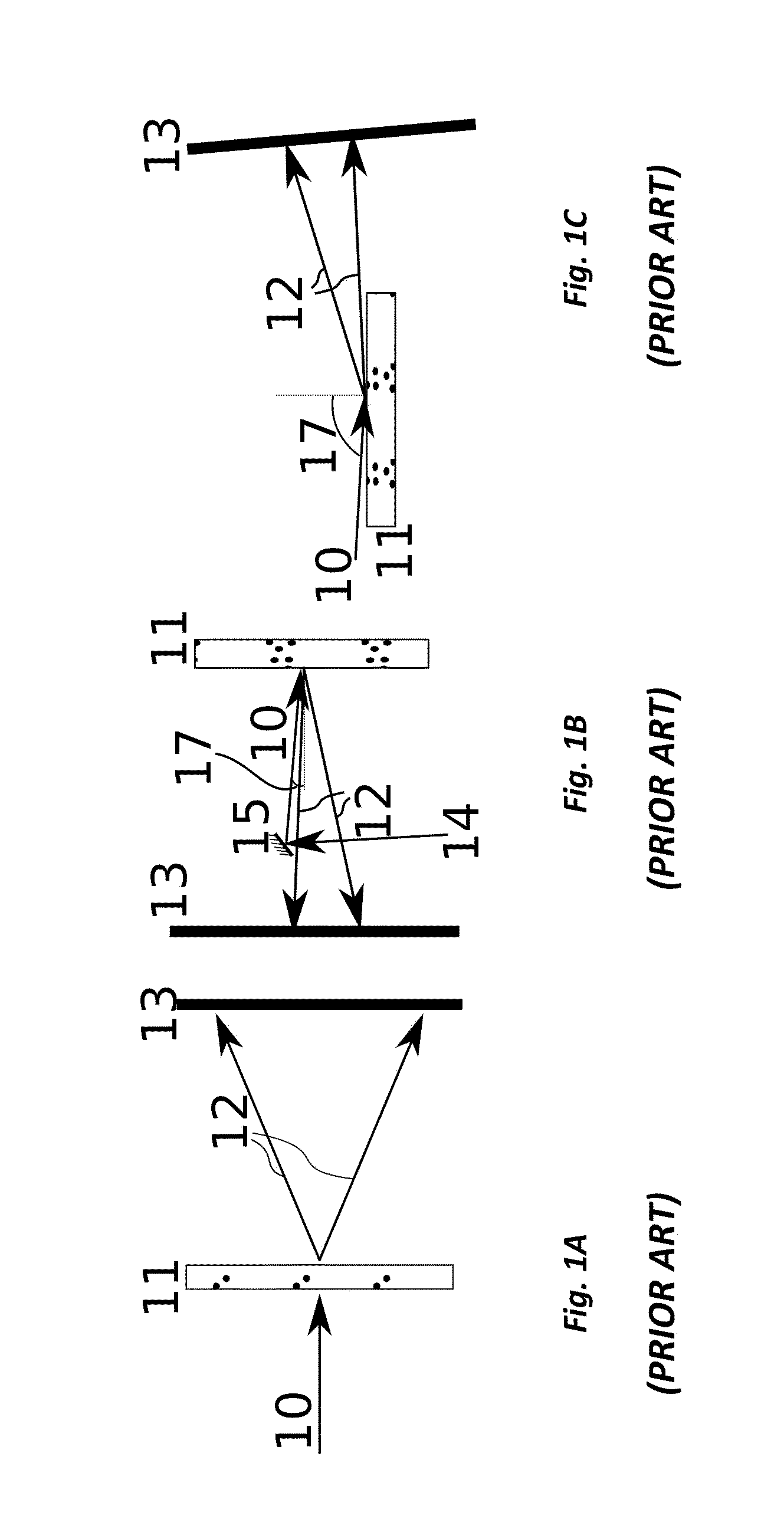
[0034]The following table of elements and reference numbers is provided for convenience.
10Incident radiation11Object12Scattering field13Detector14Incident radiation before reflection15Mirror17Angle of incidence or reflection θi20Incident radiation (transmission geometry)21Incident radiation (reflection geometry)22Object24Diffraction intensity25Detector26Diffraction intensity pattern detected27Initial (detector) grid (generally spatially uniform)28Remapped pattern on grid 2929Intermediate grid (chosen to result in uniform spatial frequencygrid 202)34Step of remapping according to the present invention35Slow conventional remapping44Fourier transform magnitude on the detector grid 2748The step of calculating the Fourier transform magnitude202Final grid (generally uniform spatial frequency)204Prior art step of converting from detector grid 27 to a non-uniformspatial frequency grid 302206Step of calculating intermediate grid 29 from final grid 202211The distance from the sample to the de...
PUM
 Abstract
Description
Claims
Application Information
 - R&D
- Intellectual Property
- Life Sciences
- Materials
- Tech Scout
- Unparalleled Data Quality
- Higher Quality Content
- 60% Fewer Hallucinations
Browse by: Latest US Patents, China's latest patents, Technical Efficacy Thesaurus, Application Domain, Technology Topic, Popular Technical Reports.
© 2025 PatSnap. All rights reserved.Legal|Privacy policy|Modern Slavery Act Transparency Statement|Sitemap|About US| Contact US: help@patsnap.com


