Method and system for controlling access to wireless apparatuses

Active Publication Date: 2016-06-02
CERTIS CISCO
View PDF9 Cites 7 Cited by
  • Summary
  • Abstract
  • Description
  • Claims
  • Application Information

AI Technical Summary

Benefits of technology

This patent describes a method for securely controlling access to an apparatus. The method involves storing a partial link key in a first apparatus and receiving a first secret key from a first source. The first apparatus then generates a link key based on the stored partial link key, the first secret key, and a second secret key from a second source. The link key can be used to establish a secure wireless connection with a second apparatus. The second apparatus can also be granted different levels of access based on the link key used. The patent also describes a system comprising two apparatuses and a supervisor apparatus. The supervisor apparatus can provide a secret key to one of the apparatuses for use in generating a link key. Overall, this patent provides a way to securely control access to an apparatus and manage access levels.

Problems solved by technology

A problem with the pairing procedure is that if a third party eavesdrops on the whole pairing procedure, they can perform brute force calculations through the space of all available PINs and obtain the link key.
This makes the task of obtaining the link key a considerably more difficult problem than previously, but in most cases it is still susceptible to a “Man in the Middle” attack.
Whether pairing is performed according to the more secure Version 2.1 specification, or earlier less secure versions, a problem exists that either device can control when a new link key is generated.
Whilst this approach provides secure bonding between the two devices, and prevents tampering of the link, this does not provide secure access control to the devices, or even guarantee that the devices are issued to appropriate personnel, for example if the user and issuer collude, or if a user inappropriately obtains the secret key allowing him to self-issue a pair of devices.
Other more general wireless communication arrangements and protocols may also suffer from this disadvantage.

Method used


Image

  • Method and system for controlling access to wireless apparatuses
  • Method and system for controlling access to wireless apparatuses
  • Method and system for controlling access to wireless apparatuses

Examples


Embodiment Construction

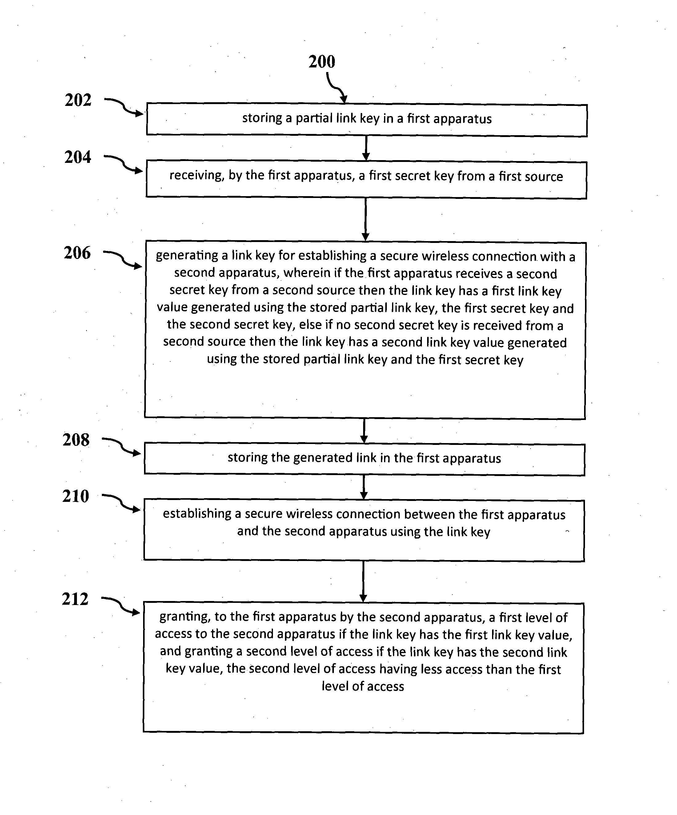
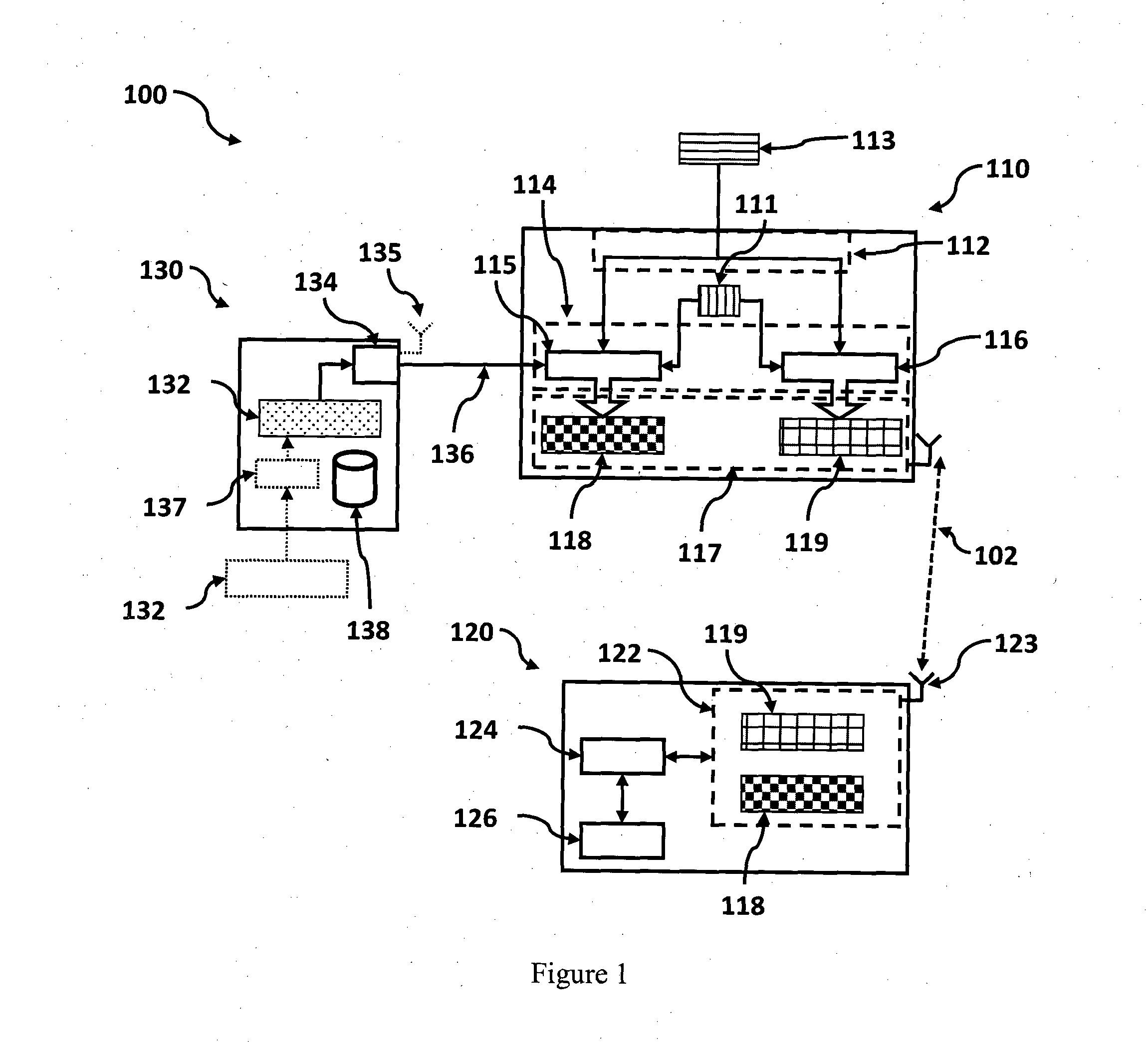
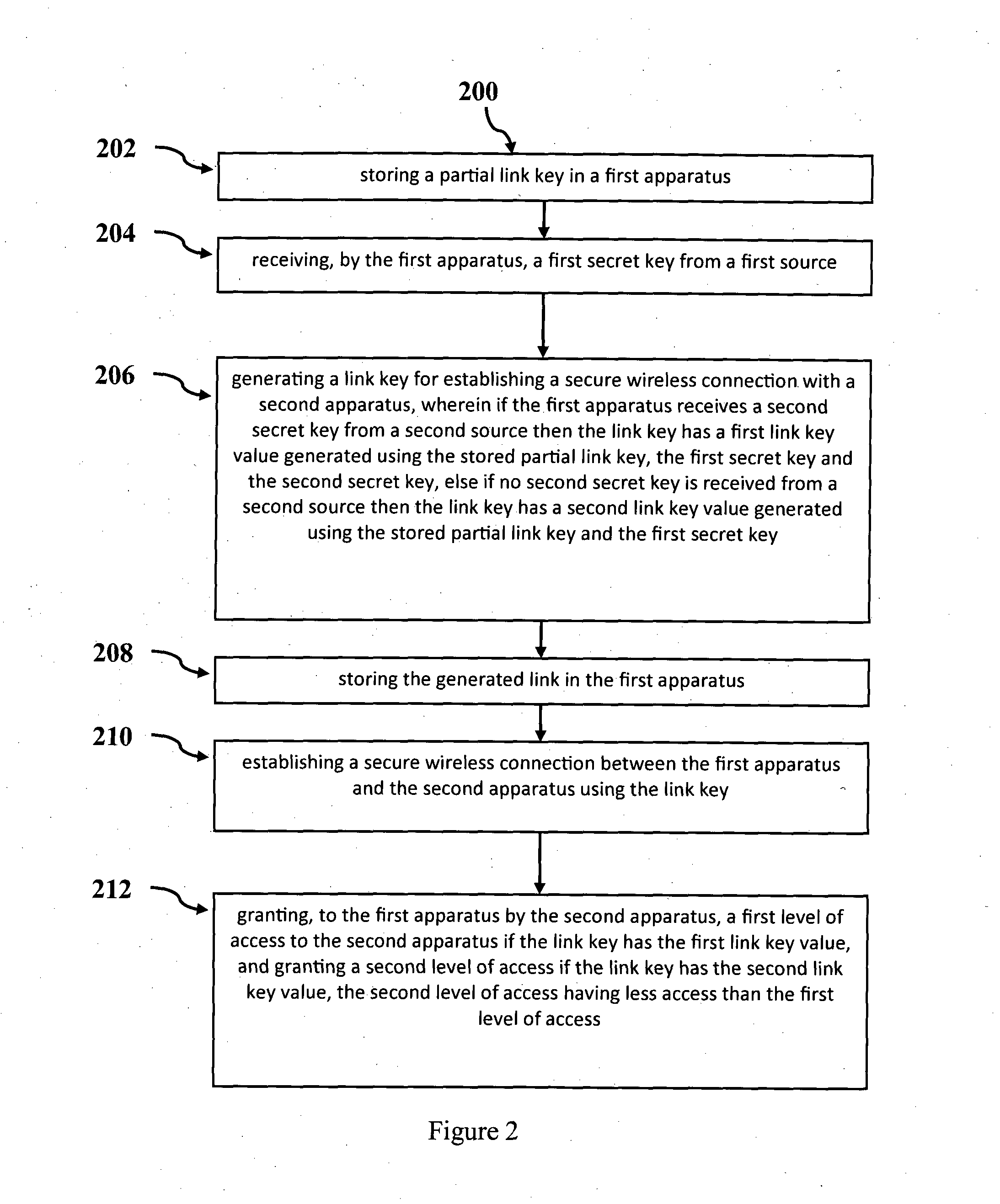
[0045]Referring now to FIG. 1, there is shown a system 100 for securely controlling access in an apparatus according to an embodiment. FIG. 2 shows a flow chart of a method 200 for securely controlling access in an apparatus implemented in the system 100 shown in FIG. 1. The terms apparatus will be used interchangeably with device, and the described functionality may be provided in a single housing or as a single component, or it can be comprised of multiple components which may be distributed provided they are functionally connected, such as by cables, wires, or wireless links.

[0046]The system 100 comprises a first apparatus 110, a second apparatus 120 and a supervisor apparatus 130. The first apparatus is paired to the second apparatus by establishing a secure wireless communications link 102. Once the secure wireless connection is established the first apparatus attempts to access functions and resources 126 provided by the second apparatus 120. An access control module 124 deter...


PUM


Abstract

A system for securely controlling access between two wireless (i.e. Bluetooth-enabled) apparatuses, also comprising a supervisor apparatus. The first apparatus is paired to the second by establishing a secure wireless (i.e. Bluetooth) link The first apparatus includes a stored partial link key and a link key generator: The first apparatus receives a first secret key from the apparatus user, and may also receive a second secret key from the supervisor apparatus. The link key generator generates either a first link key based upon a stored first partial link key, the first secret key and the second secret key or a second link key based upon the stored first partial link key and the first secret key. An access control module in the second apparatus determines the level of access that the first apparatus is granted based upon the link key used to establish the secure connection—full / restricted access.

Description

INCORPORATION BY REFERENCE[0001]The present application refers to the following documents:[0002]Singaporean Patent Number 2008057382[0003]The entire content of this document is hereby incorporated by reference.TECHNICAL FIELD[0004]The present invention relates to wireless apparatuses and in one particular form relates to methods for controlling access to a wireless apparatus.BACKGROUND[0005]The Specification of the Bluetooth System (hereafter referred to as the Bluetooth specification) defines a short range wireless communication system. The system uses frequency hopping spread spectrum technology in the unlicensed Industrial, Scientific, and Medical (ISM) 2.4 GHz short-range radio frequency band. Bluetooth is primarily designed for low power short range communications, typically using low-cost transceiver microchips embedded in devices. Devices may be assigned a class based upon the maximum permitted power, which defines an effective transmission range. Class 1 devices have a range...

Claims


Application Information

Patent Timeline
IPC IPC(8): H04L29/06H04W4/80
CPCH04L63/06H04L63/105F41A17/06G06F21/42H04L9/0838H04L9/085H04L2209/80H04W4/80H04W12/0471H04W12/041H04W12/082F41A17/00G06F21/00H04L9/00H04W12/00H04W12/08H04L2463/082H04L63/0838H04L63/0853H04L63/0492
Inventor TAN, POH BENGBAPTIST, MARTIN JAMESWONG, KEEN HONLUI, HONCHINGLI, XIANG
Owner CERTIS CISCO
Why Eureka
Try Eureka