Device and method for the decontamination of hollow objects such as container caps using UV radiations

Active Publication Date: 2016-04-14
CLARANOR
View PDF4 Cites 8 Cited by
  • Summary
  • Abstract
  • Description
  • Claims
  • Application Information

AI Technical Summary

Benefits of technology

The invention takes advantage of UV radiation transmitted and diffused through walls to decontaminate the interior surfaces of a cavity. The transmission, diffusion, and reflection effects allow light to reach even the narrowest and most distant areas of the cavity. The invention is especially efficient in reaching high levels of decontamination. The invention can also be used to decontaminate caps that are not transparent to UV, by using a translucent cap and applying a protective coating or layer.

Problems solved by technology

It causes breaches and formation of abnormal bonds in the DNA molecules which prevent proper DNA replication.
One problem with the technique of decontamination by exposure to UV radiations is that all the relevant surfaces must be exposed to an adequate level of radiations, and depending on their shapes and materials (transparent to UV or not), it may be difficult to reach them.
This problem becomes even more critical when high levels of decontamination are expected, by example for packaging products with extended duration of conservation.
. . ), but they frequently comprise patterns or shapes which are difficult to expose to UV radiations.
Furthermore, they are usually not transparent in the UV, as they are made of materials diffusing and / or absorbing in the UV.
This classical approach leads to complex systems which are still not satisfactory when high levels of decontamination are expected, because some areas are still not reachable by direct illumination (for instance the plug seal for the water- and air tightness of bottle screw caps).

Method used


Image

  • Device and method for the decontamination of hollow objects such as container caps using UV radiations
  • Device and method for the decontamination of hollow objects such as container caps using UV radiations
  • Device and method for the decontamination of hollow objects such as container caps using UV radiations

Examples


Embodiment Construction

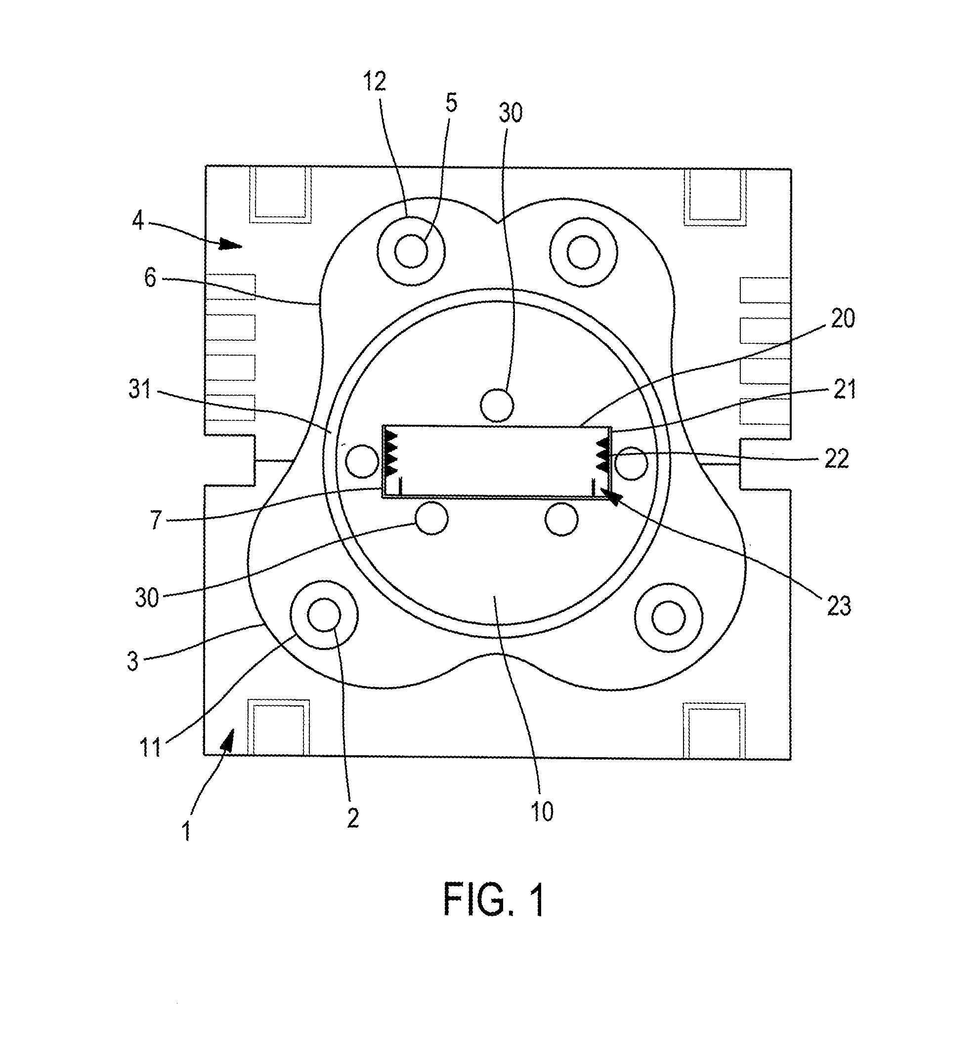
[0076]We will now describe, with reference to FIG. 1, an embodiment of the device of the invention for the decontamination of bottle caps 7 in production line.

[0077]FIG. 1 shows a cut view of an exemplary bottle screw cap 7. It comprises an internal cavity 20 surrounded by walls 21. The shape of the surfaces inside this cavity 20 is usually complex, comprising for instance a thread 22 for screwing the cap 7 on a bottle and a plug seal 23 for the air and liquid tightness.

[0078]The caps 7 are frequently made in materials at least partially translucent to UV radiations, such as for instance Polypropylene (PP), High-density polyethylene (HDPE), or polyethylene (PE).

[0079]The device of the invention comprises a decontamination zone 10 elongated in a direction of elongation, in which bottle caps 7 to be decontaminated are inserted.

[0080]The decontamination zone 10 is surrounded by first exposure means 4 and second exposure means 1.

[0081]The decontamination zone 10 is delimitated by a surr...


PUM


Abstract

A device is provided for the decontamination of hollow objects with a cavity such as caps, including: (i) a first exposure apparatus including at least a UV radiation source and a reflector oriented toward the cavity of the positioned objects, able to produce a direct exposure to UV radiations of surfaces inside the cavity, (ii) a second exposure apparatus including at least a UV radiation source placed on the opposite side relative to the cavity of the positioned objects, thes second exposure apparatus being able to expose surfaces inside the objects cavity to UV radiations by diffusion and / or transmission of UV radiations through the walls surrounding the objects cavity, and the first and second exposure apparatus cooperating for producing a global exposure to UV radiations of the surfaces inside the objects cavity. A method is also provided for the decontamination of hollow objects.

Description

FIELD OF THE INVENTION[0001]The invention relates to a device and a method for the decontamination of hollow objects such as container caps by application of ultraviolet (UV) light.[0002]The field of the invention is the decontamination of containers for the packaging in food and drugs industries.BACKGROUND OF THE INVENTION[0003]The decontamination of containers by application of pulsed or continuous UV radiations is a well known technique, widely used in particular in the food and medical industry.[0004]The technique exploits the ability of UV radiations to destroy cells and microorganisms, which is essentially due to two effects: a photochemical effect and a photothermal effect.[0005]The photochemical effect, which is obtained with pulsed and continuous UV radiations, results from the absorption by the microorganisms of the UV radiation. It causes breaches and formation of abnormal bonds in the DNA molecules which prevent proper DNA replication. The microorganism's protein product...

Claims


Application Information

Patent Timeline
IPC IPC(8): A61L2/10B08B7/00B08B9/08
CPCA61L2/10B08B7/0057B08B9/08A61L2/26B67B3/003
Inventor FRANC, JANYCEHOUDE, ERIC
Owner CLARANOR
Why Eureka
Try Eureka