
Filter medium for liquid filter and method for manufacturing same

a technology of liquid filter and filter medium, which is applied in the direction of membranes, filtration separation, separation processes, etc., can solve the problems of difficult to make fine pores not more than 1 m, difficult to create uniform pores, and difficult to make pores less than 1 m, etc., to achieve excellent air permeability and excellent water permeability

Inactive Publication Date: 2016-05-19
AMOGREENTECH CO LTD
View PDF6 Cites 36 Cited by
  • Summary
  • Abstract
  • Description
  • Claims
  • Application Information

AI Technical Summary

Benefits of technology

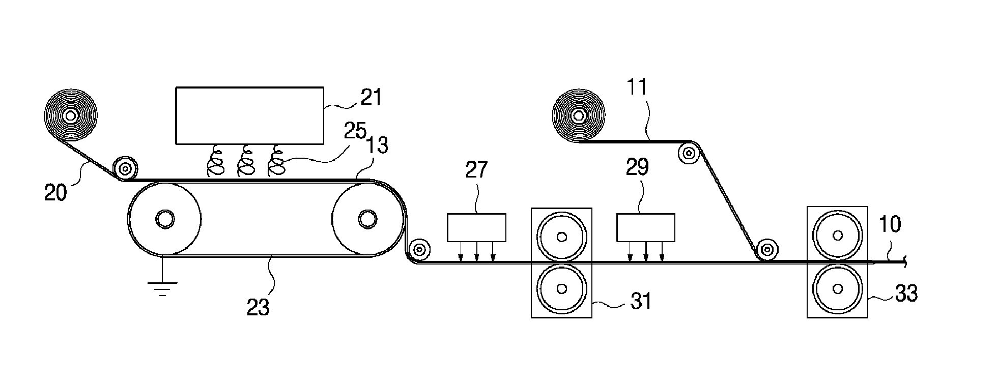
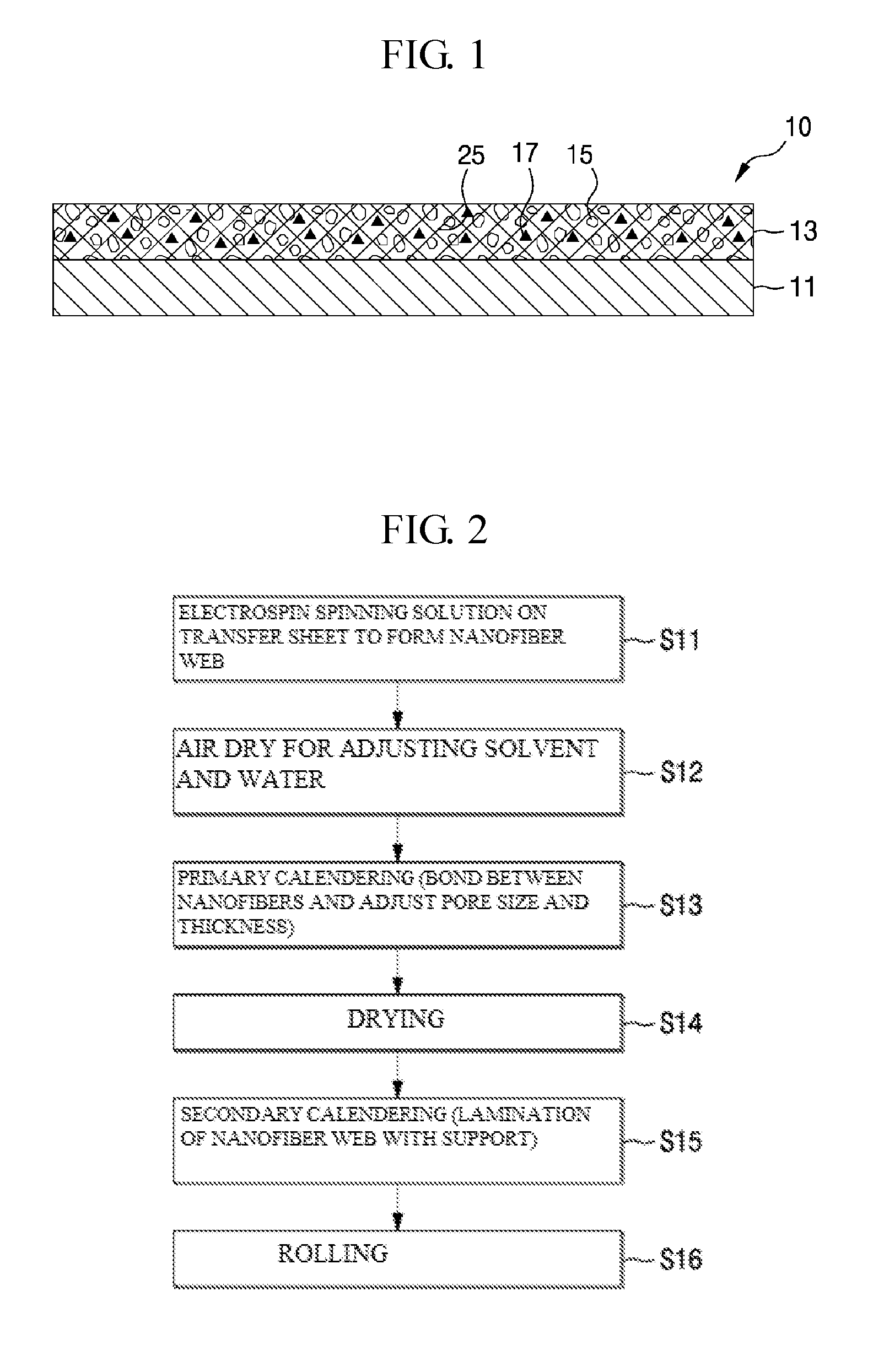
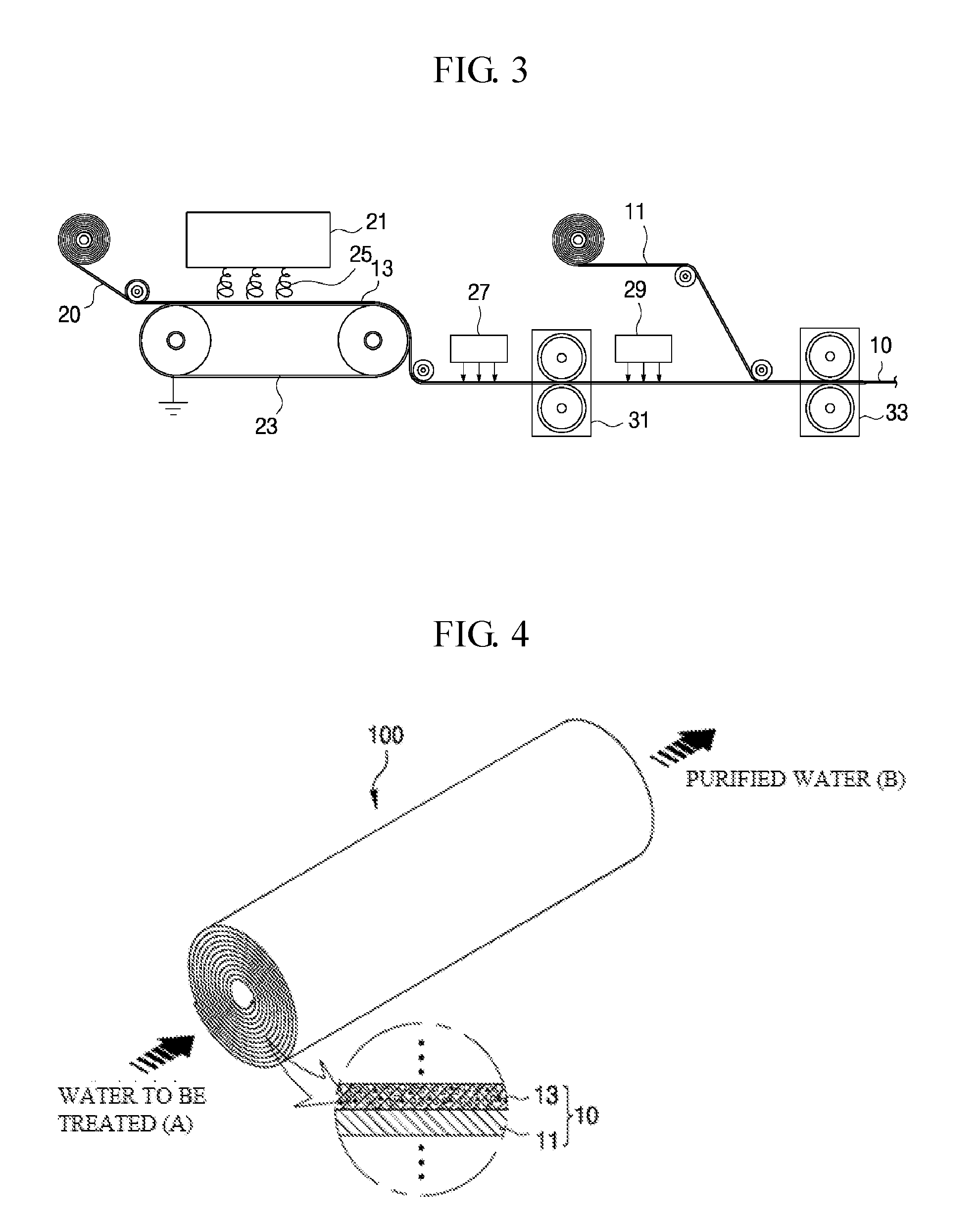
The present invention provides a filter medium for liquid filters and a method of manufacturing the same. The filter layer is made by laminating a thin layer of light weight nanofibers on a porous nonwoven fabric, resulting in a filter with excellent air and water permeability. This leads to a membrane with low differential pressure before and after filtration which increases the pass flow rate. The transfer method of spinning nanofibers on a transfer sheet and laminating it onto a nonwoven fabric provides a nanofiber web with uniformity in pore size, permeability, thickness, and weight. The calendaring process creates a rigid coupling between the nanofibers, resulting in a more robust filter medium.

Problems solved by technology

It is difficult to make pores not more than 1 μm in the case of nonwovens, wovens, meshes, etc.
Since the nonwovens, wovens, or meshes are made of fibers having a thickness from several micrometers to several hundreds of micrometers, it is difficult to make fine pores not more than 1 μm.
In particular, it is not possible actually to create uniform pores since webs are formed by random arrangement of fibers in the case of the nonwoven fabrics.
Accordingly, the nonwovens, wovens, or meshes have the difficulty in preventing the leakage of contaminated materials through relatively large pores and thus have low filter efficiency.
Therefore, the filter media are used in an inaccurate filtration process or used as a pre-treatment concept of an accurate filtration process.
While the conventional porous membranes may create pores of precise and small size, closed pores or blinded pores may be created inevitably in the manufacturing process.
As a result, the conventional porous membranes have problems such as a small flow amount of filtration, a high driving pressure, and a short filtration lift cycle, to thus cause high operating costs and frequent filter replacement.
However, the method of forming a fibrous web of nanofibers in the patent document 1 cannot be referred to a manufacturing technique that uses a multi-hole spinning pack.
In addition, when manufacturing a nanofiber web by an electrospinning method in an electrobrown spinning apparatus using a multi-hole spinning the pack in order to increase productivity, a spinning solution containing a polymer of 24 wt % increases the viscosity and is solidified at the surface of the spinning solution, to thus make it difficult to spin for a long time, and increases the fiber diameter, to thus cause a problem that it is not possible to make the fibrous form of not more than a micrometer in size.
Furthermore, in the case that the ultrafine fiber web obtained by electrospinning does not go through a pretreatment process of appropriately adjusting the amount of the solvent and moisture remaining on the surface of the web before performing calendering, pores are increased but the strength of the web is weakened.
Otherwise, in the case that evaporation of the solvent is performed too slowly, a phenomenon of melting the web may occur.
However, the process of thermo-compression bonding the support in which the nanofiber web has been formed after air-electrospinning the spinning solution on top of the support to thus form a nanofiber web, in the method of preparing the filter media for liquid filters, may use a porous nonwoven fabric having a high tensile strength as the support, to thereby increase the tensile strength and have the benefit of increasing the ease of handling during the production but may cause a problem that uniformity of the nanofiber web is not high.
Therefore, in the case of forming a nanofiber web by spinning nanofibers directly on a nonwoven fabric, as disclosed in Patent Document 2, there exist problems that a nanofiber web having excellent uniformity cannot be obtained in view of a nanofiber web pore size, permeability, thickness, weight, and so on.
In Patent Document 2, was proposed filter media that are laminated with a nanofiber web by using a nonwoven fabric made of a fiber with a single core structure such as a melt-blown nonwoven fabric, a spun bond nonwoven fabric, and a thermal bond nonwoven fabric, but it is difficult to maintain a pore structure in any one of the nonwoven fabric and the nanofiber web since calendering is performed at a relatively lower melting point of melting points of the nonwoven fabric and the nanofiber web when the nonwoven fabric and the nanofiber web are laminated on each other.
However, the heavy-weight of the filter media is a factor directly connected with a production rate, to thus cause high costs.
In addition, nanofibers have a large amount of static electricity in a manufacturing process, and thus when the filter media include only nanofibers themselves, it is quite difficult to handle the filter media.
Furthermore, although nanofibers may have good relative intensities as compared with the other fibers, the absolute strengths of nanofibers are prone to be weak.
However, when performing a calendering process by spinning a spinning solution directly onto a nonwoven fabric as disclosed in Patent Document 2, the melting point of the nonwoven fabric is lower than an inter-fiber bonding temperature of the nanofibers made of a polymer, to accordingly limit a calendering temperature control.
As a result, a rigid coupling between the nanofibers to form the nanofiber web cannot be made.
However, when preparing the filter media by using the hydrophilic polymer, there is a problem that the hydrophilic polymer is weak in the mechanical strength and the chemical resistance as compared to the hydrophobic polymer and thus should be used limitedly.
As a result, the filter media made of a PVdF polymer have a very suitable strength and chemical resistance to liquid filtration, but there is a problem that the filter media are limitedly used in aqueous filtration because of the hydrophobic property.
Accordingly, in the case that the hydrophilic treatment is performed or not, there is a problem that water does not pass through the filter media well if an appropriate force is not applied across the filter media.
In addition, in the case of making the filter media made of only nanofibers themselves of a heavy weight of about 10 g / m2 or more, a thin filter layer cannot be formed.
Thus, since a high differential pressure is applied across the filter media, there is a problem that a pass flow rate becomes little.

Method used


Image

  • Filter medium for liquid filter and method for manufacturing same
  • Filter medium for liquid filter and method for manufacturing same
  • Filter medium for liquid filter and method for manufacturing same

Examples


example 1

[0141]In Example 1, PVdF (Polyvinylidene fluoride) as a polymer material was dissolved in a solvent (DMAc:Acetone=7:3) to become 14 wt % to thus prepare a spinning solution. The spinning solution was moved to a mixing tank of an electrospinning apparatus to set a voltage applied to the electrospinning apparatus to 100 kV, a distance from a spinning nozzle and a collector to 20 cm, a discharge amount per minute to 20 μl / hole, and was electrospun under a spinning atmosphere of 30° C. and a relative humidity of 60%, to have prepared a nanofiber web of a weight of 3 gsm with a pore size of 1 μm.

[0142]The thus-obtained nanofiber web was calendered under the condition of 150° C. and 1 Kgf / cm2 thereby have formed a bond between the nanofibers and thus have implemented a fixed pore structure, and the calendered nanofiber web was laminated with a nonwoven fabric under the condition of 130° C. and 1 Kgf / cm2 to have produced a filter medium. The nonwoven fabric used in this Example 1 was a non...

example 2

[0151]In Example 2, PVdF (Polyvinylidene fluoride) as a polymer material was dissolved in a solvent (DMAc:Acetone=7:3) to become 10 wt % to thus prepare a spinning solution. The spinning solution was moved to a mixing tank of an electrospinning apparatus to set a voltage applied to the electrospinning apparatus to 100 kV, a distance from a spinning nozzle and a collector to 20 cm, a discharge amount per minute to 20 μl / hole, and was electrospun under a spinning atmosphere of 30° C. and a relative humidity of 60%, to have prepared a nanofiber web of a weight of 3 gsm with a pore size of 0.45 μm.

[0152]The thus-obtained nanofiber web was calendered under the condition of 150° C. and 1 Kgf / cm2 thereby have formed a bond between the nanofibers and thus have implemented a fixed pore structure, and the calendered nanofiber web was laminated with a nonwoven fabric under the condition of 130° C. and 1 Kgf / cm2 to have produced a filter medium. The nonwoven fabric used in this Example 2 was th...


PUM

PropertyMeasurementUnit
Thicknessaaaaaaaaaa
Thicknessaaaaaaaaaa
Diameteraaaaaaaaaa

Abstract

Provided are filter media for liquid filters and a method of manufacturing the same, in which a thin filter layer is formed and the content of nanofibers weighs light, by laminating a low weight nanofiber web on a porous nonwoven fabric, and thus a less differential pressure is applied before and after filtering, to thereby increase a pass flow rate. The filter medium includes: a porous support that plays a strength support role; and a nanofiber web that is laminated on one side of the porous support and is made of nanofibers of a polymer material, in which the nanofiber web comprises fine pores of a three-dimensional structure, through which a liquid to be treated passes, wherein content of the nanofibers is less than 5 gsm.

Description

TECHNICAL FIELD[0001]The present invention relates to filter media for liquid filters and a method of manufacturing the same, and more particularly, to filter media for liquid filters and a method of manufacturing the same, in which a thin filter layer is formed and the content of nanofibers weighs light, by laminating a low weight nanofiber web on a porous nonwoven fabric, and thus a less differential pressure is applied before and after filtering, to thereby increase a pass flow rate.BACKGROUND ART[0002]Recent industrial advancement has required high purity and high quality of products, and thus a separator (or a membrane) technology has been recognized as a very important field. In the environmental sector, especially as the need for clean water and the awareness of a lack of water increases, a technology of using a membrane has largely attracted much attention as one of ways to solve these problems. Processes such as water purification, sewage, waste water, and desalination usin...

Claims


Application Information

Patent Timeline
IPC IPC(8): B01D69/12
CPCB01D69/12B01D69/10D04H1/728B01D2323/39B01D2325/42B32B5/26D01D5/003B32B5/00B29C70/504B01D2239/025B01D2239/065B01D2239/0654B32B5/022B32B5/08B32B2262/0238B32B2262/0253B32B2262/0276B32B2262/04B32B2262/12B32B2264/0228B32B2264/0235B32B2264/10B32B2307/718B32B2307/726B32B2307/728B32B2307/73B32B2307/732B01D39/1623B01D69/122B01D69/1071B01D69/1213B01D2325/40B01D2325/0283
Inventor HWANG, JUN SIKSEO, IN YONG
Owner AMOGREENTECH CO LTD
Learn More