
Gas turbine engine fuel system

a fuel system and gas turbine engine technology, applied in the ignition of turbine/propulsion engines, engine starters, lighting and heating apparatus, etc., can solve the problems of increasing so as to reduce the cost of fuel consumption and reduce waste. the effect of redundancy

Inactive Publication Date: 2016-04-21
ROLLS ROYCE PLC
View PDF11 Cites 21 Cited by
  • Summary
  • Abstract
  • Description
  • Claims
  • Application Information

AI Technical Summary

Benefits of technology

The invention provides a fuel system that can still provide enough fuel to the engine even if there is a single electrical fault in one of the electrical motors. The system uses multiple stator windings to ensure electrical redundancy and maintain the required pumping capacity. The system also allows for independent control of oil pump speed and reduces waste by using a variable displacement pump or valves. This arrangement provides a reliable and redundant system that is not affected by a single electrical failure.

Problems solved by technology

However, conventional fuel systems have several known problems.
They require relatively high power demands, since the pump delivers an excess of fuel at all times, with a proportion recirculated.
This arrangement is therefore relatively inefficient, leading to higher pump power requirements, and therefore increased fuel consumption, compared to a system in which only the required fuel flow is pumped.
The FMU and the recirculation of the fuel can also increase the temperature of fuel flowing therethrough, leading to lacquering of the fuel, which may lead to blockages and limit the ability to use fuel as coolant.
However, it is a likely requirement for certification of gas turbine engines for civil aviation use that no one electrical failure (such as a short circuit) can result in an inability to supply the engine with sufficient fuel to run at full power.
Consequently, redundant (i.e. completely separate, additional) or fault tolerant electrical motors are required, resulting in additional cost, complexity and weight.
Since failure of the fuel system would result in shutdown of the engine, redundancy is required.
Such an arrangement leads to increased weight and complexity.
Valves in this part of the fuel system are also known to cause airlocks and fuel degradation in the fuel line, leading to blockages.
Power electronics units add considerable cost and weight to an electrical system, and take up considerable space.
In a separate problem, gas turbine engines also require an oil system to ensure supply of lubricant during use.
The oil system is considered essential for safe operation of the engine, since lack of lubricant can rapidly lead to bearing and transmission overheating, and in some cases increased engine wear and possibly engine shut down.
However, since the oil pump is an essential item for safe operation of the engine, redundancy must be provided for the oil pump.
The provision of a further two electric motors and corresponding power electronics units to drive the oil pump may reduce the amount of weight saved by the deletion of the gearbox, or may even increase the weight of the system.

Method used


Image

  • Gas turbine engine fuel system
  • Gas turbine engine fuel system
  • Gas turbine engine fuel system

Examples


Embodiment Construction

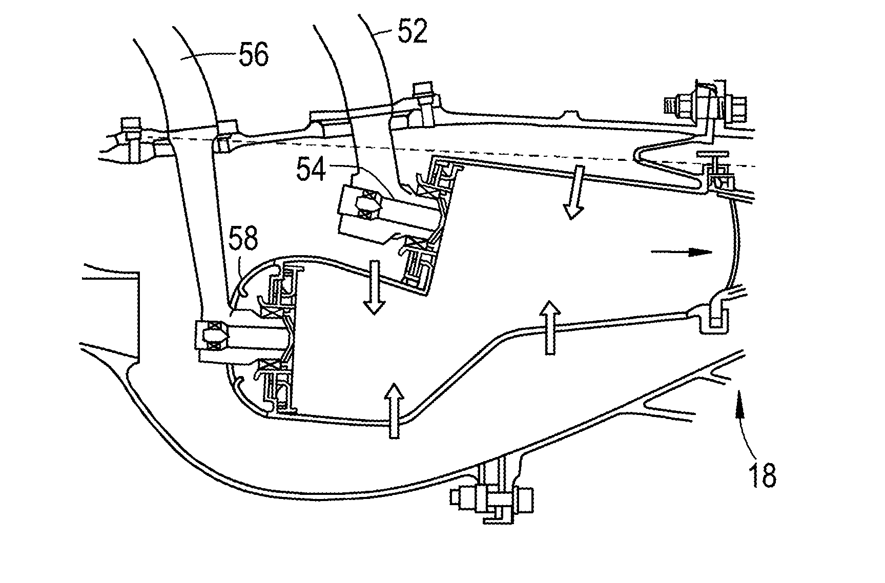
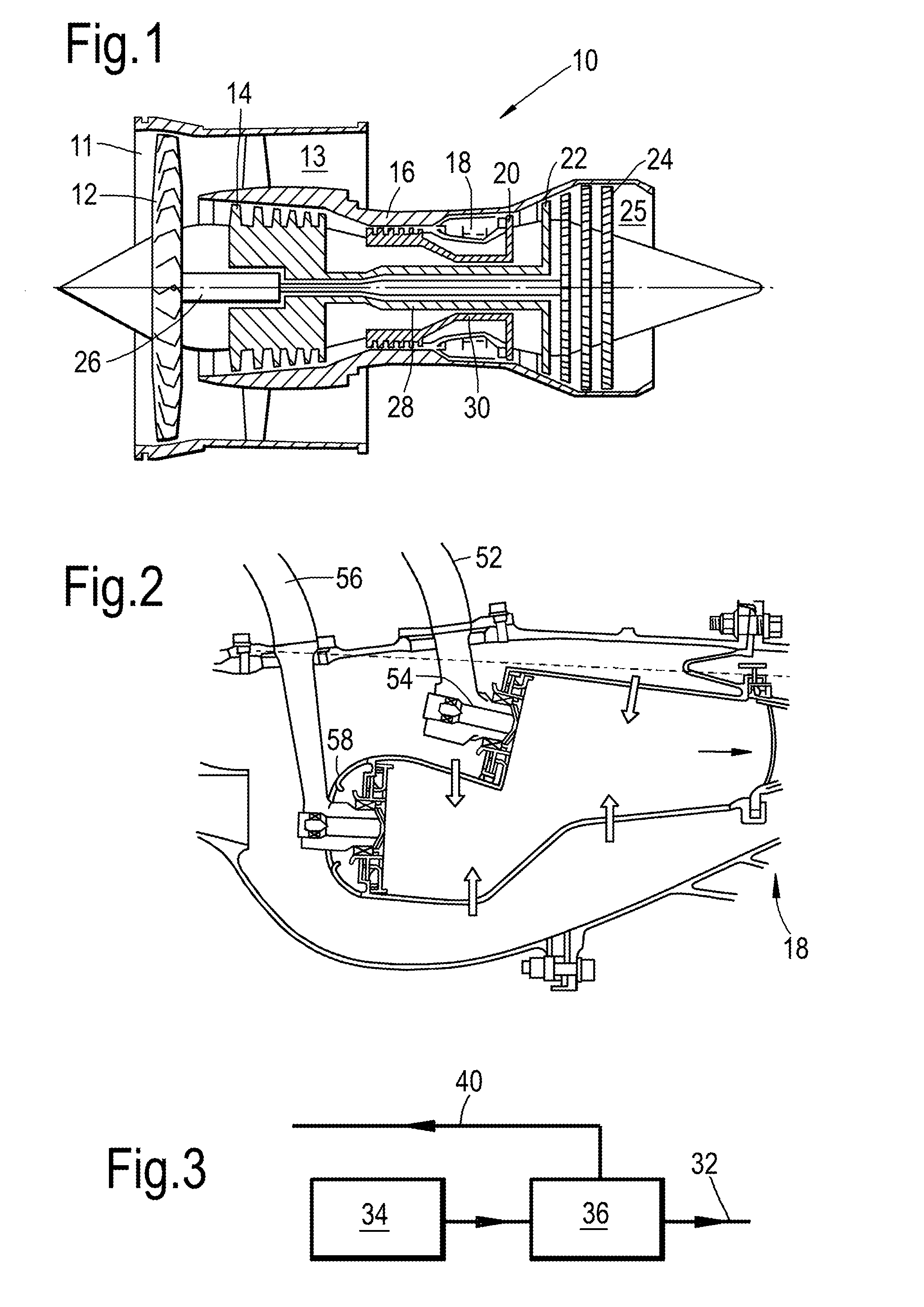
[0042]FIG. 1 shows a high-bypass gas turbine engine 10. The engine 10 comprises, in axial flow series, an air intake duct 11, an intake fan 12, a bypass duct 13, an intermediate pressure compressor 14, a high pressure compressor 16, a combustor 18, a high pressure turbine 20, an intermediate pressure turbine 22, a low pressure turbine 24 and an exhaust nozzle 25. The fan 12, compressors 14, 16 and turbines 20, 22, 24 all rotate about the major axis of the gas turbine engine 10 and so define the axial direction of gas turbine engine.

[0043]Air is drawn through the air intake duct 11 by the intake fan 12 where it is accelerated. A significant portion of the airflow is discharged through the bypass duct 13 generating a corresponding portion of the engine 10 thrust. The remainder is drawn through the intermediate pressure compressor 14 into what is termed the core of the engine 10 where the air is compressed. A further stage of compression takes place in the high pressure compressor 16 b...


PUM


Abstract

A fuel system for a gas turbine engine, the gas turbine engine including a combustor having a pilot fuel injector and a main fuel injector, the fuel system including first and second variable flow fuel pumps configured to provide metered fuel flow to the pilot injector, and the main injector respectively; first and second variable speed electric motors configured to drive respective first and second fuel pumps; wherein each of the electric motors includes a polyphase motor including a stator having concentrated windings.

Description

FIELD OF THE INVENTION[0001]The present invention relates to a fuel system for a gas turbine engine, and a gas turbine engine comprising a fuel system.BACKGROUND TO THE INVENTION[0002]FIG. 1 shows a high-bypass gas turbine engine 10. The engine 10 comprises, in axial flow series, an air intake duct 11, an intake fan 12, a bypass duct 13, an intermediate pressure compressor 14, a high pressure compressor 16, a combustor 18, a high pressure turbine 20, an intermediate pressure turbine 22, a low pressure turbine 24 and an exhaust nozzle 25. The fan 12, compressors 14, 16 and turbines 20, 22, 24 all rotate about the major axis of the gas turbine engine 10 and so define the axial direction of gas turbine engine.[0003]Air is drawn through the air intake duct 11 by the intake fan 12 where it is accelerated. A significant portion of the airflow is discharged through the bypass duct 13 generating a corresponding portion of the engine 10 thrust. The remainder is drawn through the intermediate...

Claims


Application Information

Patent Timeline
IPC IPC(8): F23R3/28F02C7/236F04D13/06F02C7/275
CPCF23R3/28F02C7/275F05D2220/32F04D13/06F02C7/236F02C7/228F02C9/26F02C9/34F05D2220/76H02P5/74Y02T50/60
Inventor EDWARDS, HUW LLEWELYNSCANLON, TIMOTHY JOHNWANG, YICULLEN, JOHN JAMES ANTHONY
Owner ROLLS ROYCE PLC
Learn More