
Laser Guided and Laser Powered Energy Discharge Device

a laser guided and laser-powered technology, applied in the direction of instruments, mass spectrometers, beam deviation/focusing by electric/magnetic means, etc., can solve the problem that the formation of large volume highly energized plasma is still non-deterministic to some degree, and achieves convenient and efficient transmission of electromagnetic signals, convenient and efficient condu

Inactive Publication Date: 2016-04-07
WEIGOLD DR ADAM MARK
View PDF0 Cites 28 Cited by
  • Summary
  • Abstract
  • Description
  • Claims
  • Application Information

AI Technical Summary

Benefits of technology

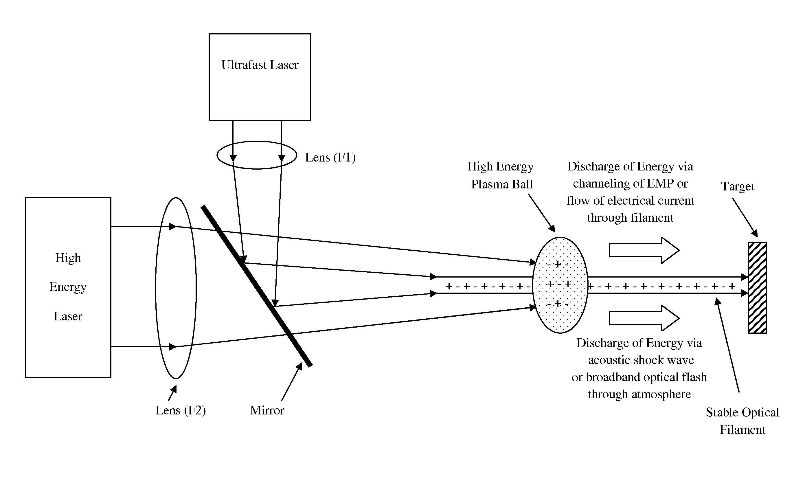
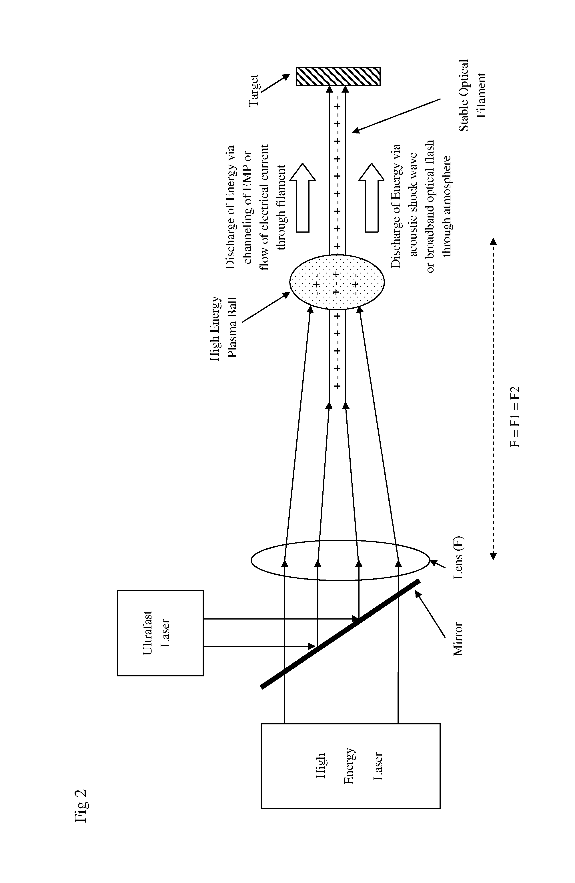
The patent describes a process of using a high energy laser to power a plasma volume in a target. The laser focuses its energy onto a small area along the optical filament, creating a highly energized plasma that can be controlled and directed towards the target. The plasma has the potential to store a significant amount of energy and discharge it into the target, resulting in a large volume of combined plasma with potential for significant energy density and impact. The process of seeding the plasma with the laser is non-deterministic and may not be critical for the effectiveness of the invention. The invention only requires that the large volume plasma overlap with the optical filament to some degree, and the potential for seeding is minimal. The high energy plasma can produce both an electrical and an optical pulse that can be efficiently transmitted down the optical filament to the target, resulting in optical blinding and missile countermeasure applications.

Problems solved by technology

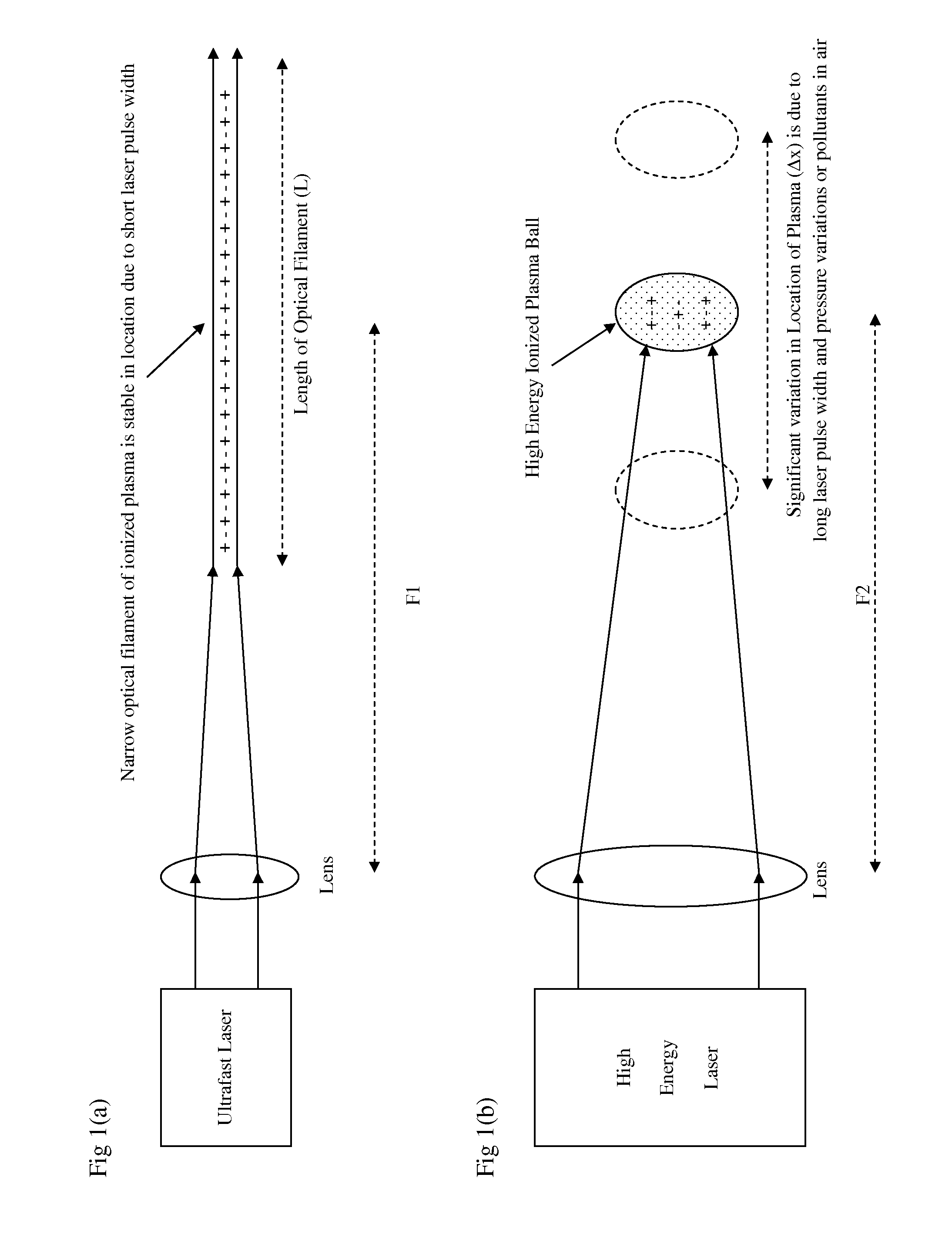
However the two plasmas typically have vastly different spatial characteristics, volumes and plasma densities so this seeding effect may occur only near the limited volume of plasma overlap.
Furthermore the relatively long time scale of the high energy laser pulse means that the formation of the large volume highly energized plasma is still non-deterministic to some degree.

Method used


Image

  • Laser Guided and Laser Powered Energy Discharge Device
  • Laser Guided and Laser Powered Energy Discharge Device
  • Laser Guided and Laser Powered Energy Discharge Device

Examples


Embodiment Construction

[0034]In a preferred embodiment of the invention, as a first step the output from an ultrafast laser is focused by a lens such that a narrow optical filament is formed in air. The convergence of the laser beam is balanced against the divergence of the defocusing effects from laser blooming such that the length of the optical filament is of the order of several meters or more. In addition, the process of creating an optical filament may be assisted or seeded with the use of phase plates or a diffracting aperture along the path of laser propagation. The ultrafast laser output may be produced from, but is not limited to, non-linear frequency multiplication of a mode-locked solid-state laser such as a Titanium doped Sapphire laser or a Neodymium doped Glass laser. Non-linear frequency multiplication can convert the infrared output from a laser to the ultraviolet spectrum which typically ionizes a gas with greater efficiency than infrared laser output and can also be focused to a smaller...


PUM


Abstract

The present invention relates to a laser guided and powered directed energy weapon that combines two different lasers to accurately and efficiently deliver a high energy electromagnetic pulse (EMP) to a target at long range. The method uses a high energy laser pulse with relatively long pulse duration focused in air to create a plasma ball which emits an intense EMP. Typically the long pulse duration of high energy lasers would severely limit focal accuracy and effective range because of air pressure variations and pollutants in the atmosphere. However the present invention uses a second ultrafast laser to create a long thin optical plasma filament between the variable location of the plasma ball and the target to act as a stable electrical connection or conducting wire. Consequently EMP can be efficiently channeled to the target via the optical filament, thereby dramatically increasing potential accuracy, range and energy delivery efficiency.

Description

REFERENCE TO RELATED APPLICATIONS[0001]This application is related to and claims priority from U.S. provisional Application No. 61 / 563,617 filed Nov. 25, 2011 entitled Laser Guided and Laser Powered Energy Discharge Device which is incorporated fully herein by reference.STATEMENT REGARDING FEDERALLY SPONSORED RESEARCH OR DEVELOPMENT[0002]Not ApplicableREFERENCE TO SEQUENCE LISTING, A TABLE, OR A COMPUTER PROGRAM LISTING COMPACT DISC APPENDIX[0003]Not ApplicableTECHNICAL FIELD OF THE INVENTION[0004]The present invention relates to a method of using a laser based device to produce electrically charged or ionized plasma in air which can discharge energy in various forms to a target with applications including use as a directed energy weaponBACKGROUND OF THE INVENTION[0005]The use of laser based devices as directed energy weapons for the purpose of causing disorientation, damage or destruction of a target is well known. Various laser based devices have been developed for use against a v...

Claims


Application Information

Patent Timeline
IPC IPC(8): F41H13/00G21K5/10G21K1/00H01S3/23H01S3/00
CPCF41H13/0062H01S3/23G21K5/10G21K1/003H01S3/005H01S3/0092H01S3/2391H05G2/00
Inventor WEIGOLD, ADAM MARK
Owner WEIGOLD DR ADAM MARK
Learn More