Eureka AIR delivers breakthrough ideas for toughest innovation challenges, trusted by R&D personnel around the world.

Method for Increasing the Roughness of Injector Gripper Blocks for Coiled Tubing Operations

a technology of injector gripper block and injector head, which is applied in the direction of solid-state diffusion coating, drilling pipes, and well accessories, etc., can solve the problems of coiled tubing b>30/b> to become damaged, compromising the integrity of coiled tubing, and the cost of replacing coiled tubing strings, etc., to achieve the effect of increasing the roughness of coiled tubing injector gripper blocks

Active Publication Date: 2016-04-07
BAKER HUGHES INC
View PDF9 Cites 1 Cited by
  • Summary
  • Abstract
  • Description
  • Claims
  • Application Information

AI Technical Summary

Benefits of technology

This patent describes a method to make the gripping surfaces of coiled tubing injector gripper blocks rougher, to improve the process of injecting coiled tubing into a wellbore. This can be done by adding a coating of chromium carbide, molybdenum boride, or other materials to the gripping surfaces, or by treating the surfaces to increase their roughness. This roughness compensates for any reduction in roughness caused by a lubricant used on the coiled tubing. The technical effect is smoother operation of the coiled tubing injector and better sealing of the wellbore.

Problems solved by technology

Slippage of the coiled tubing 30 may cause at least two problems.
Slippage may cause the coiled tubing 30 to become damaged.
For example, slippage within the injector head 100 may cause the coiled tubing 30 to be gouged, potentially compromising the integrity of the coiled tubing, which may result in the expense of replacing the coiled tubing string.
Slippage of the coiled tubing 30 through the coiled tubing 30 may interfere with precise positioning during well intervention operations.

Method used


Image

  • Method for Increasing the Roughness of Injector Gripper Blocks for Coiled Tubing Operations
  • Method for Increasing the Roughness of Injector Gripper Blocks for Coiled Tubing Operations
  • Method for Increasing the Roughness of Injector Gripper Blocks for Coiled Tubing Operations

Examples


Embodiment Construction

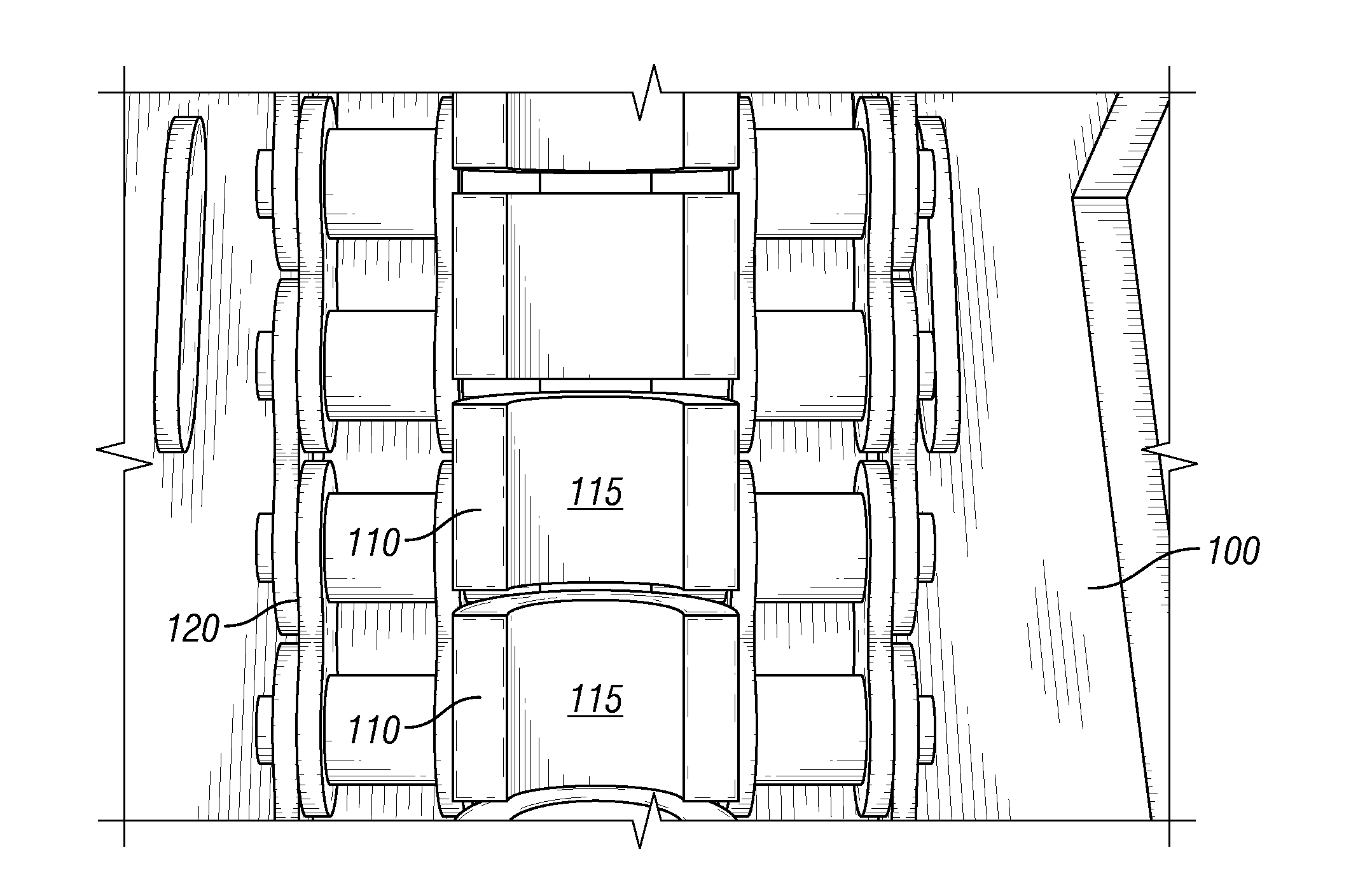
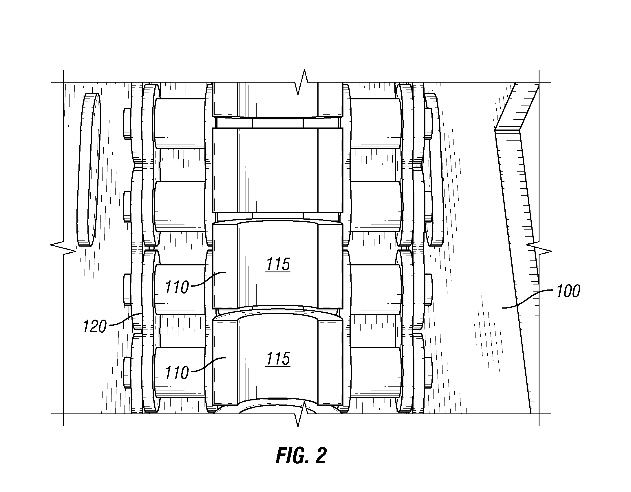
[0020]FIG. 2 shows a plurality of gripper blocks 110 positioned within an injector head 100. The gripper blocks 110 each include a gripping surface 115 that is forced against coiled tubing 30 to provide a normal force against the coiled tubing 30. Two gripper blocks 110 (only one side is shown in FIG. 2) on either side of the coiled tubing 30 hold the coiled tubing 30 in place with a friction force. A chain 120 connected to the gripper blocks 110 may be rotated around a motor to advance the coiled tubing 30 into the wellhead 80 or pull the coiled tubing 30 out of the wellhead 80.

[0021]FIG. 3 shows a pair of gripper blocks 110 that could be used to support coiled tubing 30 within an injector head 100. The friction force, Ff, must be equal to or greater than the weight, Wt, of the coiled tubing 30 in order to adequately support the coiled tubing 30 within the injector head. The friction force, Ff, is equal to the normal force, Fn, applied to the coiled tubing 30 by the gripping surfac...


PUM

PropertyMeasurementUnit
roughnessaaaaaaaaaa
roughnessaaaaaaaaaa
roughnessaaaaaaaaaa

Abstract

A method of increasing a roughness of coiled tubing injector blocks that includes providing a pair of gripper blocks each having a gripper surface configured to grip coiled tubing within an injector head and increasing a first roughness on the gripping surfaces to a second roughness. A coating may be applied to the gripping surfaces to increase the roughness. The coating may be chromium carbide, molybdenum boride, iron boride, titanium boride, or a transitional metal boride. The gripping surfaces may be treated to increase the roughness to a second roughness. The gripping surfaces may be blasted by abrasives or shot peened to increase the roughness. The second roughness may be greater than 20 μm. A system to inject coiled tubing into a wellbore may include an injector head, coiled tubing, and at least two gripper blocks having a gripping surface with a roughness of at least 20 μm.

Description

BACKGROUND[0001]1. Field of the Disclosure[0002]The embodiments described herein relate to a method and system to increase the roughness of the gripping surface of coiled tubing injector head gripper blocks.[0003]2. Description of the Related Art[0004]Coiled tubing is used in various wellbore operations. FIG. 1 shows a trailer mounted coiled tubing reel 20 that stores the coiled tubing 30 prior to insertion into the wellhead 80. The coiled tubing 30 is unreeled and nominally straightened prior to insertion into the wellhead 80. An operator in a control cabin 10 controls the insertion of the coiled tubing 30. The coiled tubing 30 travels along a gooseneck 40 and into an injector head 100. A crane 50 is used to suspend the injector head 100 above the wellhead 80. Gripping blocks within the injector head 100 grip the coiled tubing 30 and are used to insert the coiled tubing 30 into the wellhead 80 as well as to remove the coiled tubing 30 from the wellhead 80. A stuffing box 60 positio...

Claims


Application Information

Patent Timeline
Patent Type & Authority Applications(United States)
IPC IPC(8): E21B17/20B24C1/06C23C8/68C23C8/08E21B19/22C23C4/10
CPCE21B17/20E21B19/22B24C1/06C23C8/68C23C8/08C23C4/10
Inventor LIVESCU, SILVIUSISTA, VIVEKANANDDELOREY, JOHNWATKINS, THOMAS J.
Owner BAKER HUGHES INC
Why Eureka
Eureka Blog
Learn More