
Shrouded bonded turbine rotors and methods for manufacturing the same

Inactive Publication Date: 2016-03-24
HONEYWELL INT INC
View PDF11 Cites 0 Cited by
  • Summary
  • Abstract
  • Description
  • Claims
  • Application Information

AI Technical Summary

Benefits of technology

This patent describes methods and apparatus for manufacturing a shrouded bonded turbine rotor. The technical effects of this invention include improved performance and efficiency of turbine engines through the use of a shrouded blade ring and a hub bonded together. The resulting rotor has better resistance to high temperatures, reduced vibration, and increased durability. This design also allows for the integration of advanced materials and manufacturing techniques, further improving the performance and functionality of the rotor.

Problems solved by technology

High OPR gas turbine engines include high-pressure turbines with low corrected flows and small blade span heights, resulting in excessive tip clearance losses.
Turbine rotors used in high-pressure (HP) turbines typically have reduced blade solidity (blade count) for a variety of reasons, resulting in a greater pitch-wise distance between the turbine blades, creating higher bending stresses at the interface between the turbine blade airfoils and a shroud.
Such bending stresses are aggravated by the fact that HP turbines normally operate at high rotational speeds and temperatures (e.g., greater than 1700 feet / second tip speed and greater than 1500° Fahrenheit (° F.) metal temperature), resulting in reduced fatigue life and burst problems.
As such, turbine rotors used in high-pressure turbines are not amenable to the tip-shrouded turbine blades of conventional turbine rotors used in low-pressure (LP) turbines.
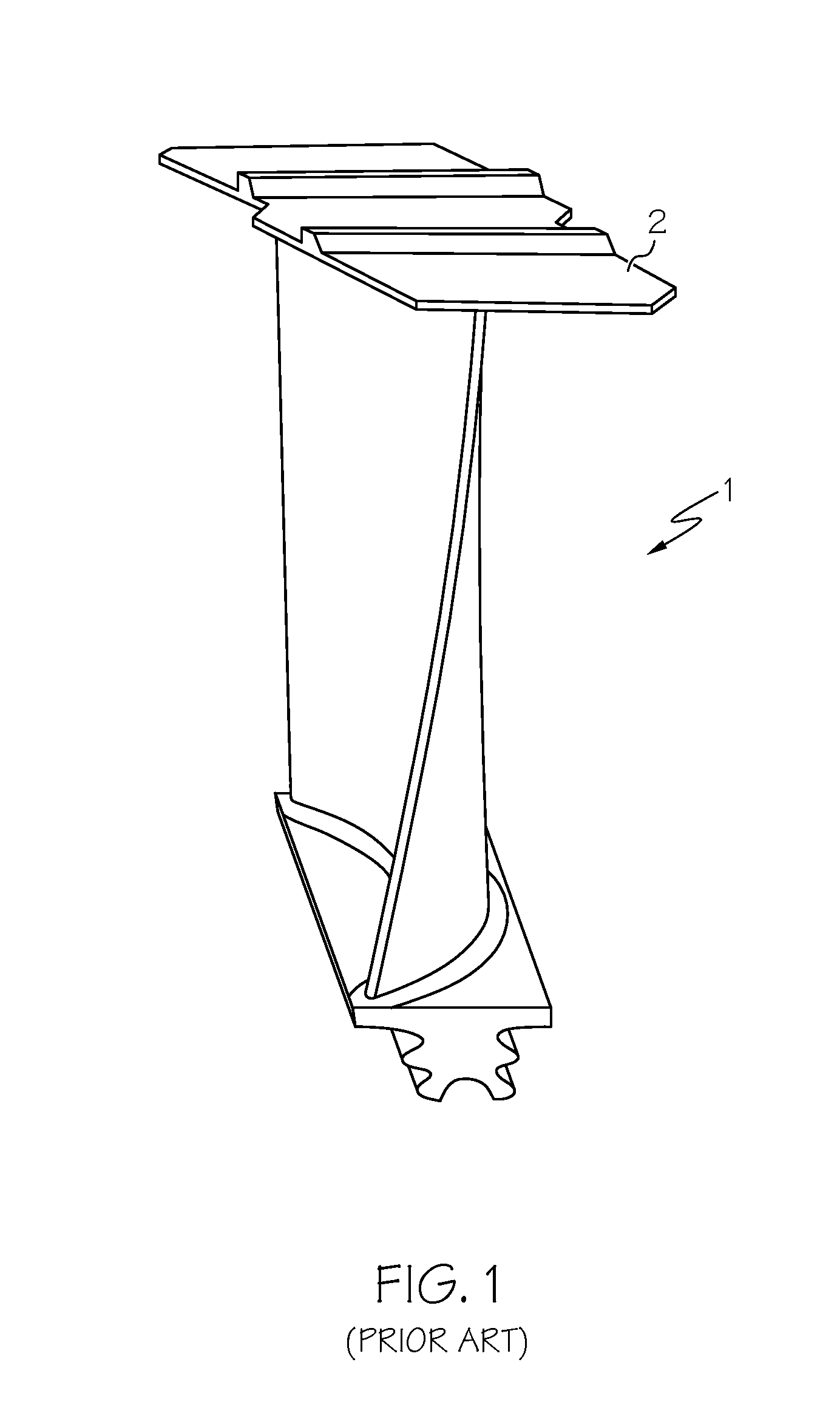
As a result, bending stress of the overhung shroud segment 2 on the airfoil tip of the tip-shrouded turbine blade segment 1 in the conventional turbine rotor may occur and there may be excessive leakage between the overhung shroud segments 2 when used in a high-pressure turbine.
Tip-shrouded turbine blades that are integrally cast as a full ring in the conventional dual alloy turbine rotor as previously described are also not particularly amenable to use in a high-pressure turbine rotor, being limited to the lower strength and lower temperature-capable equi-axed alloys (i.e., equi-axed alloys (e.g., MAR-M-247® alloy) have lower strength at elevated temperatures (relative to the strength at elevated temperatures of single crystal and directionally solidified alloys)).

Method used


Image

  • Shrouded bonded turbine rotors and methods for manufacturing the same
  • Shrouded bonded turbine rotors and methods for manufacturing the same
  • Shrouded bonded turbine rotors and methods for manufacturing the same

Examples


Embodiment Construction

[0026]The following detailed description is merely exemplary in nature and is not intended to limit the invention or the application and uses of the invention. As used herein, the word “exemplary” means “serving as an example, instance, or illustration.” Thus, any embodiment described herein as “exemplary” is not necessarily to be construed as preferred or advantageous over other embodiments. All of the embodiments described herein are exemplary embodiments provided to enable persons skilled in the art to make or use the invention and not to limit the scope of the invention which is defined by the claims. Furthermore, there is no intention to be bound by any expressed or implied theory presented in the preceding technical field, background, brief summary, or the following detailed description.

[0027]Various embodiments are directed to shrouded bonded turbine rotors and methods for manufacturing the same. The shrouded bonded turbine rotors according to exemplary embodiments advantageo...


PUM

PropertyMeasurementUnit
Temperatureaaaaaaaaaa
Pressureaaaaaaaaaa

Abstract

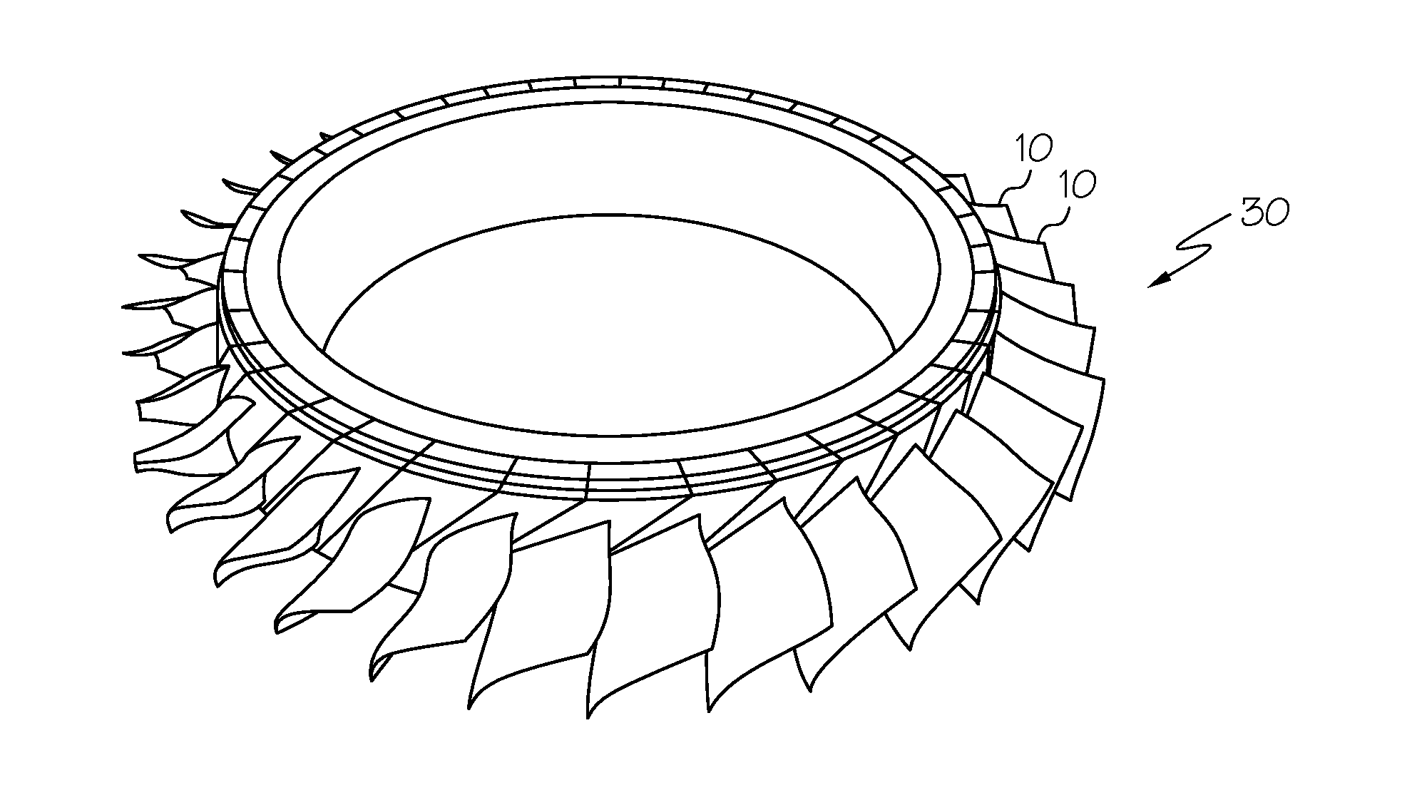
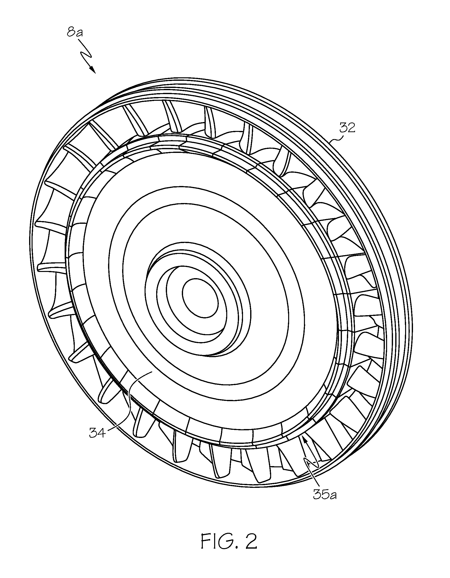
Methods are provided for manufacturing a shrouded bonded turbine rotor. A shrouded blade ring is formed. The shrouded blade ring is formed by bonding a unitary shroud ring to an assembled blade ring or assembling a plurality of shrouded turbine blade segments. The shrouded blade ring is bonded to a hub. The shrouded bonded turbine rotors are also provided. The shrouded bonded turbine rotor comprises a shrouded blade ring and a shroud. The shrouded blade ring comprises a plurality of turbine blade segments and a shroud. Each turbine blade segment comprises an airfoil portion including an airfoil having a root and a tip. The shroud covers the tip of each airfoil in the shrouded blade ring. A hub is bonded with the shrouded blade ring.

Description

TECHNICAL FIELD[0001]The present invention generally relates to gas turbine engines, and more particularly relates to shrouded bonded turbine rotors and methods for manufacturing the same.BACKGROUND[0002]Aircraft gas turbine engines including auxiliary power units (APUs) and main propulsion engines may incorporate dual alloy turbine (DAT) rotors. A conventional dual alloy turbine rotor comprises a blade ring made of a first alloy having a desired characteristic and a hub of a second alloy having another different desired characteristic. For example, hubs have been formed from alloys that have high tensile strength and low-cycle fatigue resistance. Blade rings that are exposed to the higher temperatures of the combustion gas path and higher centrifugal loads have been integrally cast as one piece (hereinafter a “unitary blade ring”) from equi-axed alloys that have high stress rupture and creep resistance. The hub is fabricated separately from the blade ring. Hot isostatic pressing (H...

Claims


Application Information

Patent Timeline
IPC IPC(8): F01D11/12B23P15/04F01D5/22
CPCF01D11/125F01D5/225B23P15/04B23K20/02B23P15/006F01D5/3061F01D5/34F05D2230/232B23K20/233B23K2101/001B23K2103/18B23K2103/26
Inventor KAHRS, MICHAELHOEK, TIMOTHY, VANDERBEDROSYAN, LORISSMOKE, JASONRIAHI, ARDESHIRCRITES, DANIEL, C.
Owner HONEYWELL INT INC
Learn More