Receptacle connector

a technology for receptacles and connectors, applied in the direction of coupling contact members, fixed connections, coupling device connections, etc., can solve the problems of increasing the height of the entire audio connector, occupying more space, and complicated punching process, etc., to achieve high material utilization rate, simple punching process, and low waste

Active Publication Date: 2016-03-17
LOTES
View PDF2 Cites 0 Cited by
  • Summary
  • Abstract
  • Description
  • Claims
  • Application Information

AI Technical Summary

Benefits of technology

The present invention is a receptacle connector with multiple terminals formed by direct punching with one strip. The terminals are designed in a way that ensures their elasticity and full use of materials. Compared to other related art, the connector has several advantages including simplifying the punching process, ensuring high material utilization rate, and low waste.

Problems solved by technology

However, the foregoing positioning of terminals increases the height of the entire audio connector and occupies more space.
Further, because terminals having different functions need to be formed by punching by using multiple sets of molds, the punching process is complicated.
Although such a ring-form arrangement ensures the length of the arm of force of each terminal, a large quantity of raw materials is needed to perform separate punching.
Further, connection by multiple strips is required, and direct punching and fabrication by using one strip become impossible.

Method used


Image

  • Receptacle connector
  • Receptacle connector
  • Receptacle connector

Examples


second embodiment

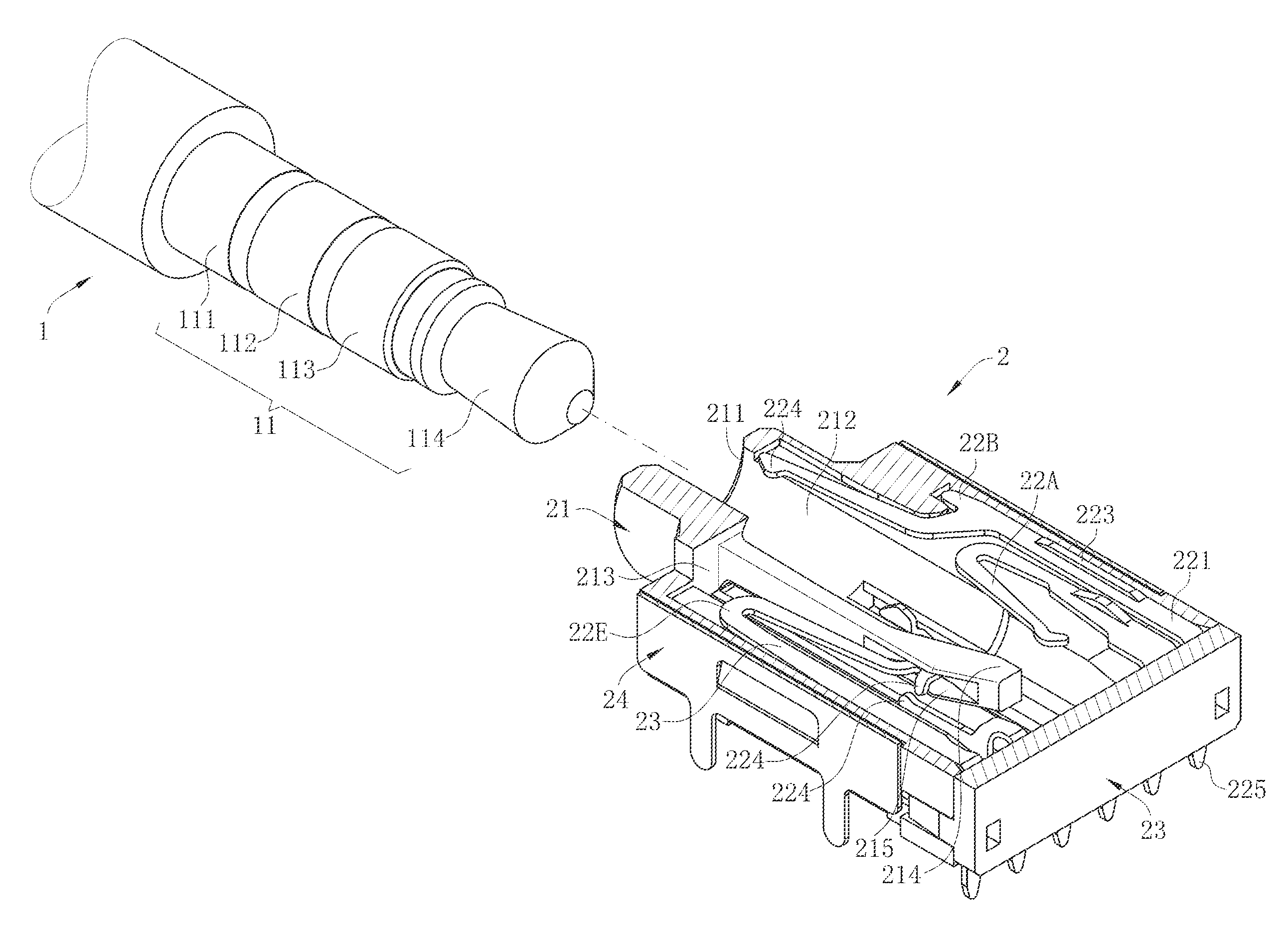
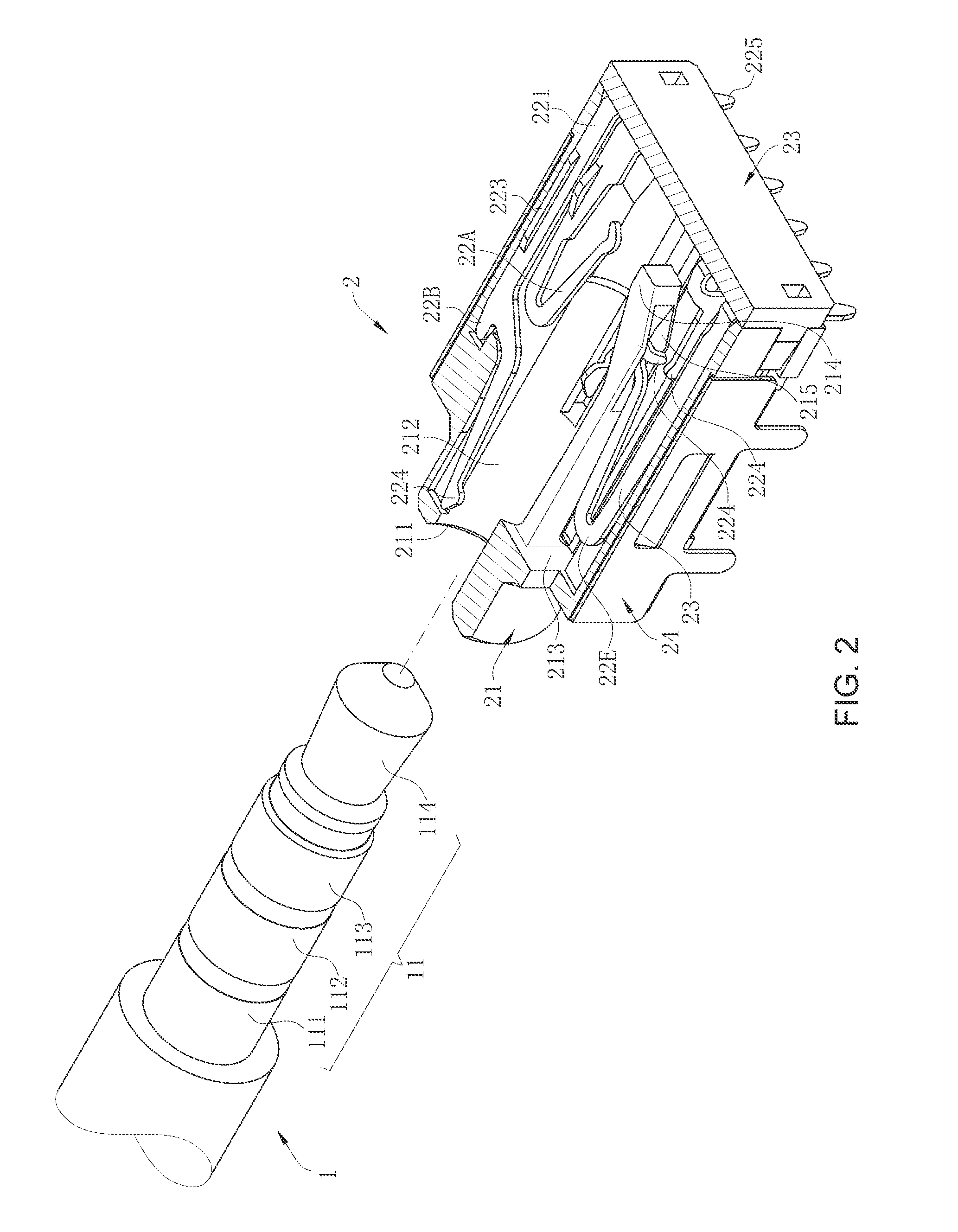
[0050]In a second embodiment, the contact portion 224 of the movable terminal 22E is formed directly from the extending arm 223 of the movable terminal 22E without bending. In this way, the contact portion 224 of the movable terminal 22E is a blanking surface contacting a plate surface of the contact portion 224 of the fixed terminal 22F. The movable terminal 22E has desirable elasticity and a large movable space.

third embodiment

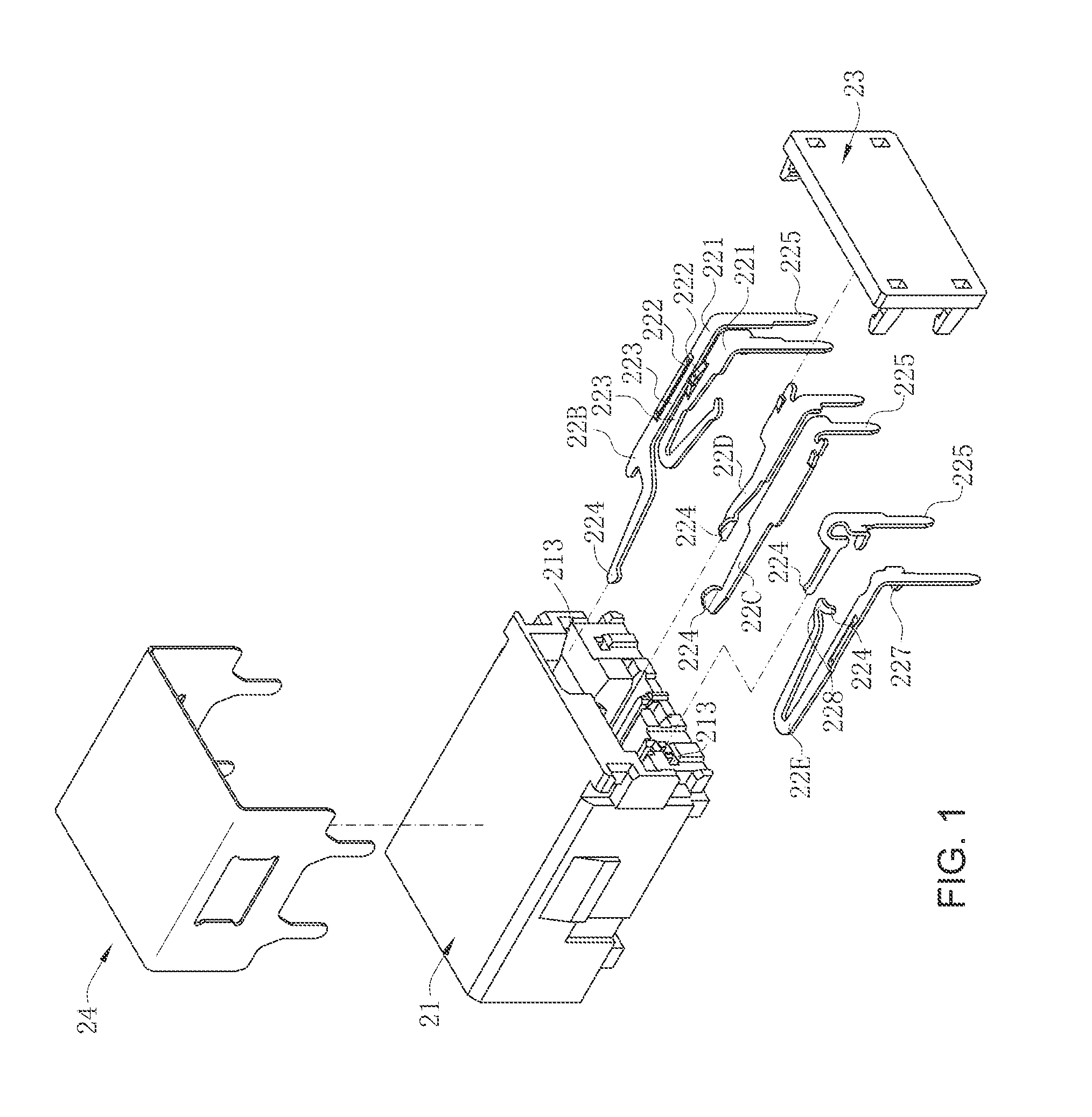
[0051]As shown in FIG. 1 and FIG. 8, in a third embodiment, the extending arm 223 of the fixed terminal 22F bends and extends forward directly from the body portion 221. The extending arm 223 of the fixed terminal 22F and the extending arm 223 of the movable terminal 22E are disposed in parallel. The contact portion 224 is formed by bending from a side of the extending arm 223. The contact portion 224 and the extending arm 223 are disposed with an obtuse angle between the contact portion 224 and the extending arm 223. In this way, the contact portion 224 of the fixed terminal 22F is also a plate surface contacting a plate surface of the contact portion 224 of the movable terminal 22E. The fixed terminal 22F has high rigidity and has a large normal force in the contact with the movable terminal 22E.

fourth embodiment

[0052]In a fourth embodiment, the extending arm 223 of the fixed terminal 22F bends and extends forward directly from the body portion 221. The extending arm 223 of the fixed terminal 22F and the extending arm 223 of the movable terminal 22E are disposed in parallel. The contact portion 224 is also formed directly from the extending arm 223 without bending. In this way, the contact portion 224 of the fixed terminal 22F is a blanking surface contacting a plate surface of the contact portion 224 of the movable terminal 22E. Only the contact portion 224 of the movable terminal 22E is bent. The fixed terminal 22F has high rigidity and has a large normal force in the contact with the movable terminal 22E.


PUM


Abstract

A receptacle connector for a male end of an audio plug connector to be inserted therein, includes an insulating body having an interface and a receiving cavity extended backwards from the interface, and at least one first terminal and two second terminals disposed inside the insulating body. The first terminal is located on a side of the male end, and has an extending arm in a plate-type U form. The two second terminals are disposed below or above the male end. All terminals are formed by punching a same strip and each have a soldering portion. The soldering portions are located on a same plane. The two second terminals contact two different contact regions away from a tail end of the male end. The first terminal contacts a contact region that adjoins the tail end of the male end.

Description

CROSS-REFERENCE TO RELATED APPLICATION[0001]This non-provisional application claims priority under 35 U.S.C. §119(a) on Patent Application No. 201420528250.8 filed in P.R. China on Sep. 11, 2014, the entire contents of which are hereby incorporated by reference.[0002]Some references, if any, which may include patents, patent applications and various publications, may be cited and discussed in the description of this invention. The citation and / or discussion of such references, if any, is provided merely to clarify the description of the present invention and is not an admission that any such reference is “prior art” to the invention described herein. All references listed, cited and / or discussed in this specification are incorporated herein by reference in their entireties and to the same extent as if each reference was individually incorporated by reference.FIELD OF THE INVENTION[0003]The present invention relates to a receptacle connector, and more particularly to an audio recepta...

Claims


Application Information

Patent Timeline
IPC IPC(8): H01R13/24H01R24/58
CPCH01R13/2464H01R2107/00H01R2105/00H01R24/58H01R12/58H01R13/7033H04R2420/09
Inventor MA, LIANG, LIANG
Owner LOTES
Why Eureka
Try Eureka