
Iron-based catalyst and method for preparing the same and use thereof

a technology of iron-based carbides and catalysts, which is applied in the field of iron-based catalysts, can solve the problems of limited improvement of catalyst performance, large amount of iron-based carbides in catalysts, and complicated preparation of metal/carbide/oxide structures, etc., and achieves superior productivity and selectivity, superior effect in low-temperature fischer-tropsch synthesis, and high productivity

Active Publication Date: 2016-02-18
KOREA INST OF ENERGY RES
View PDF7 Cites 46 Cited by
  • Summary
  • Abstract
  • Description
  • Claims
  • Application Information

AI Technical Summary

Benefits of technology

The present invention provides a method for making liquid or solid hydrocarbons using iron-based catalysts in the Fischer-Tropsch synthesis. These catalysts contain at least 30% iron atoms in iron hydroxide and at most 50% iron atoms in iron carbide. This results in high productivity and selectivity for C5+ hydrocarbons and inhibits the production of unwanted byproducts. These catalysts also exhibit superior catalytic performance. The method using these catalysts can promote the production of C5+ and C19+ hydrocarbons, which are the main products required, and inhibit the production of CO2, CH4, and C2 to C4 hydrocarbons.

Problems solved by technology

Iron-based carbides have been known as a main active species in the iron-based catalysts, and various structures of metal / carbide / oxide are prepared complicatedly during reduction and reaction.
Accordingly, when the iron-based catalysts were compared with Co-, Ni-, and Ru-based catalysts, which were merely used as metal active species, the performance thereof was highly dependent on the reduction conditions, and studies to simply increase the amount of iron-based carbides in catalysts showed limited improvement of catalyst performance.
Specifically, the conventional studies showed limitations in inhibiting the formation of the unwanted byproducts CO2, CH4, and C2 to C4 hydrocarbons, and increasing the productivity of liquid hydrocarbons having at least 5 carbons (C5+).

Method used


Image

  • Iron-based catalyst and method for preparing the same and use thereof
  • Iron-based catalyst and method for preparing the same and use thereof
  • Iron-based catalyst and method for preparing the same and use thereof

Examples


experimental example 1

Characterization of as-Prepared Catalysts

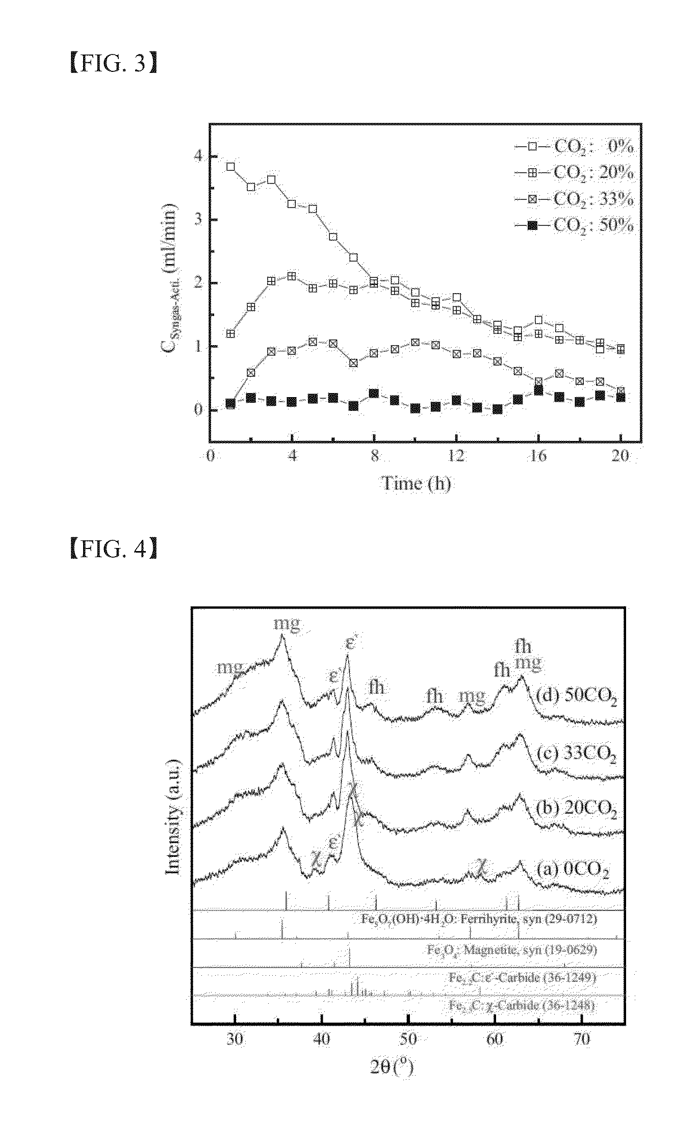
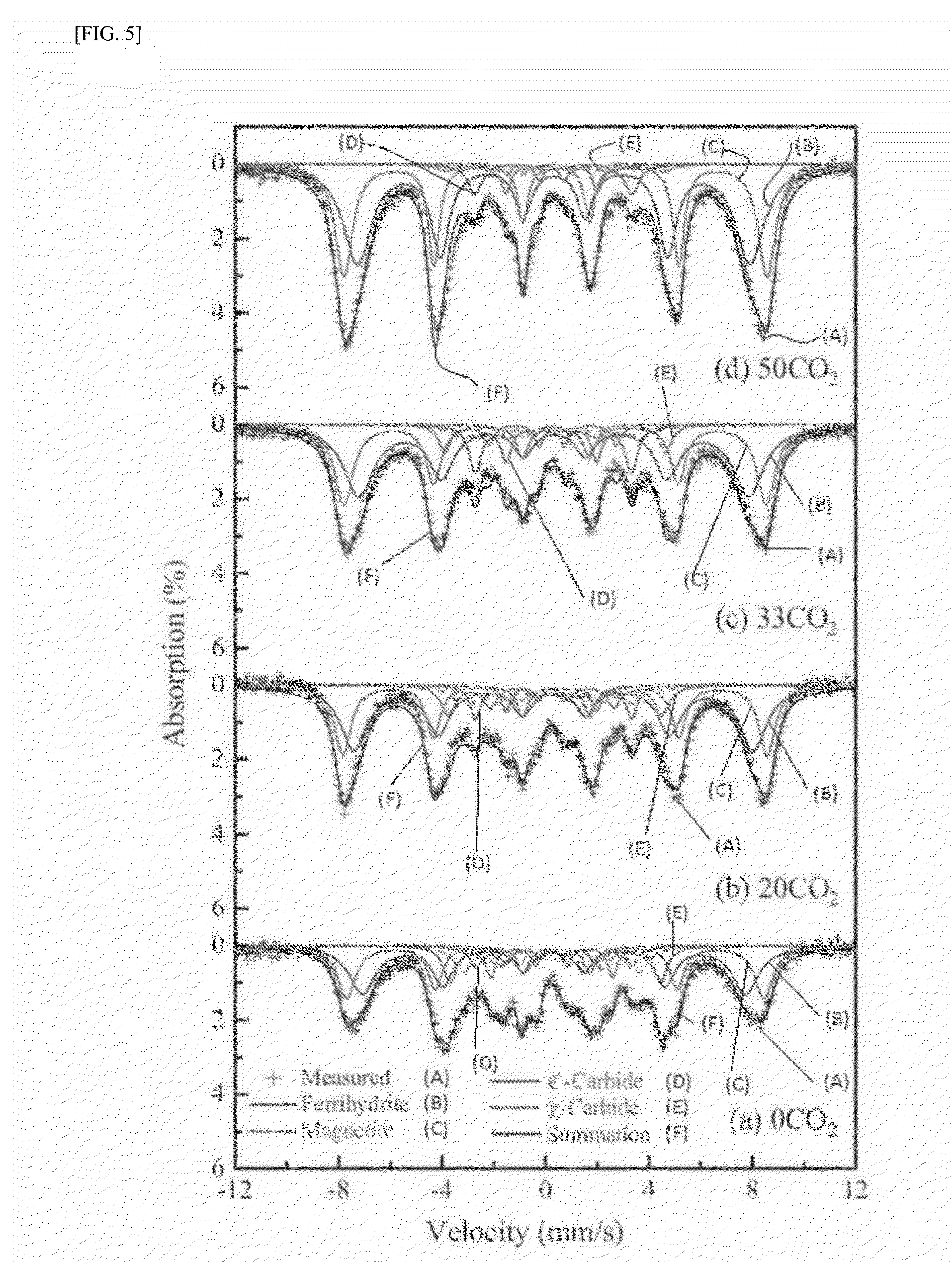
[0122]The chemical composition of the as-prepared catalysts in Example 1 was analyzed by χ-ray fluorescence spectroscopy (XRF) using a Rigaku model ZSX Primus II. Further, the Brunauer-Emmett-Teller (BET) surface area, the single point pore volume, and the average pore diameter of the as-prepared catalysts were analyzed by means of N2 physisorption using a Micrometrics model Tristar II 3020. The crystal structure of the as-prepared catalysts was characterized by χ-ray diffraction (XRD) with a Rigaku DMAX-2500 using a Cu Kα source. The quantitative analysis on the phase structure was carried out by Mössbauer spectroscopy using a 50 mCi 57Co source in a rhodium matrix. The spectrometer was operated in the constant acceleration mode, and the spectra were recorded at −268.8° C. (=4.2 K) with a fixed absorber and a moving source. The spectra were deconvoluted based on the value of magnetic hyperfine field (Hhf), isomer shift (δ), and quadruple spl...

experimental example 2

Investigation of the Influence of CO2 on the Reduction and Carburization Behavior of the Catalysts

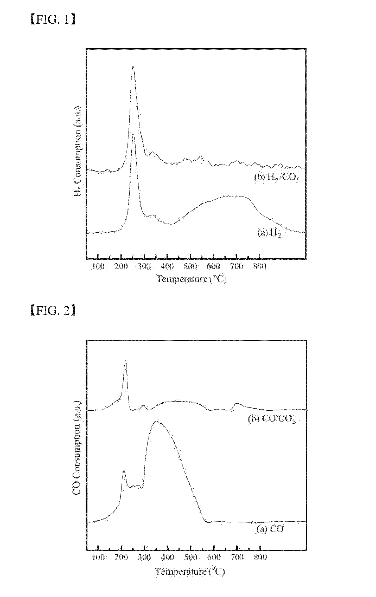
[0124]The influence of CO2 on the reduction and carburization behavior of the catalysts was analyzed by means of temperature-programmed reduction using H2 (H2-TPR) or CO (CO-TPR) as a reducing agent. Two different carrier gases were used for each reducing agent: 5% H2 / Ar and 5% H2 / 5% CO2 / Ar for the H2-TPR and 5% CO / He and 5% CO / 5% CO2 / He for the CO-TPR. The TPR was performed at up to 800° C. at a heating rate of 6° C. / min, and the temperature was then held at the maximum temperature for 60 min. During the H2-TPR process, the amount of H2 or CO2 consumption was analyzed with a quadruple mass spectrometer (MS) with a capillary inlet system. For the CO-TPR, the amount of CO consumption was measured by a thermal conductivity detector (TCD). Ascarite (223921, Aldrich) was used as a CO2 removal trap to measure the true CO consumption profiles without considering the influence of CO2 prepared ...

example 2

Preparation of Activated Catalysts

[0132]The activated catalysts for characterization were prepared by exposing the as-prepared catalysts in Example 1 to the various activation environments. After exposing the catalysts to the activation environment for 20 hours, the reactor was cooled to room temperature and pressurized to 0.3 MPa. The reactor containing the activated catalysts was unloaded from the main reactor system using quick connectors (Swagelok. SS-QC4-D-400 and SS-QC4-B-200 for inlet and SS-QC6-D-600 and SS-QC6-B-600 for outlet) and transferred to a glove box in a N2 atmosphere (purity: 99.999%). After carefully withdrawing the activated catalysts from the reactor, the catalysts were washed with hexane to remove residual liquid / solid hydrocarbons from the catalysts. The catalysts were passivated with a gas mixture of 1% O2 in He at room temperature.


PUM

PropertyMeasurementUnit
pressureaaaaaaaaaa
temperatureaaaaaaaaaa
weight ratioaaaaaaaaaa

Abstract

The present invention relates to a method for preparing liquid or solid hydrocarbons from syngas via the Fischer-Tropsch synthesis in the presence of iron-based catalysts, the iron-based catalysts for the use thereof, and a method for preparing the iron-based catalysts; more specifically, in the Fischer-Tropsch reaction, liquid or solid hydrocarbons may be prepared specifically with superior productivity and selectivity for C5+ hydrocarbons using the iron-based catalysts comprising iron hydroxide, iron oxide, and iron carbide wherein the number of iron atoms contained in the iron hydroxide is 30% or higher, and the number of iron atoms contained in the iron carbide is 50% or lower, relative to 100% of the number of iron atoms contained in the iron-based catalysts.

Description

TECHNICAL FIELD[0001]The present invention relates to iron-based catalysts capable of preparing hydrocarbons at high selectivity by optimizing phase fractions of iron hydroxide, iron oxide, and iron carbide, a preparation method thereof, and a method for preparing liquid or solid hydrocarbons from syngas in the presence of the iron-based catalysts via the Fischer-Tropsch synthesis.BACKGROUND ART[0002]The Fischer-Tropsch synthesis first began with the development of a technique that produced synthetic fuels from syngas by gasification of coal, by German chemists Fischer and Tropsch in 1923. The Fischer-Tropsch synthesis is a reaction that converts syngas to hydrocarbons in the presence of a catalyst. Herein, an increase in the selectivity of the catalyst used may increase the productivity of hydrocarbons having at least 5 carbons (C5+ hydrocarbons), an indicator of general productivity, thereby increasing the overall carbon efficiency.[0003]Group VIII metals such as iron (Fe), cobalt...

Claims


Application Information

Patent Timeline
Patent Type & Authority Applications(United States)
IPC IPC(8): B01J27/22B01J37/03B01J37/08C10G2/00
CPCB01J27/22C10G2/332B01J37/031B01J37/08B01J37/03B01J37/18B01J23/8892B01J23/78B01J23/80B01J37/0045B01J35/613B01J35/633B01J35/647B01J35/615B01J2235/00B01J35/70B01J2235/15B01J35/30
Inventor CHUN, DONG HYUNPARK, JI CHANJUNG, HEONLEE, HO-TAEYANG, JUNG-ILHONG, SUNGJUN
Owner KOREA INST OF ENERGY RES
Learn More