Superconducting devices by optimization of the superconductor's local critical current
a superconductor and local critical current technology, applied in the direction of superconductor devices, superconducting magnets/coils, magnetic bodies, etc., can solve the problems of superconductivity loss and conventional designs do not address this problem, and achieve the effect of reducing overall ac loss and increasing overall critical curren
- Summary
- Abstract
- Description
- Claims
- Application Information
AI Technical Summary
Benefits of technology
Problems solved by technology
Method used
Image
Examples
example 1
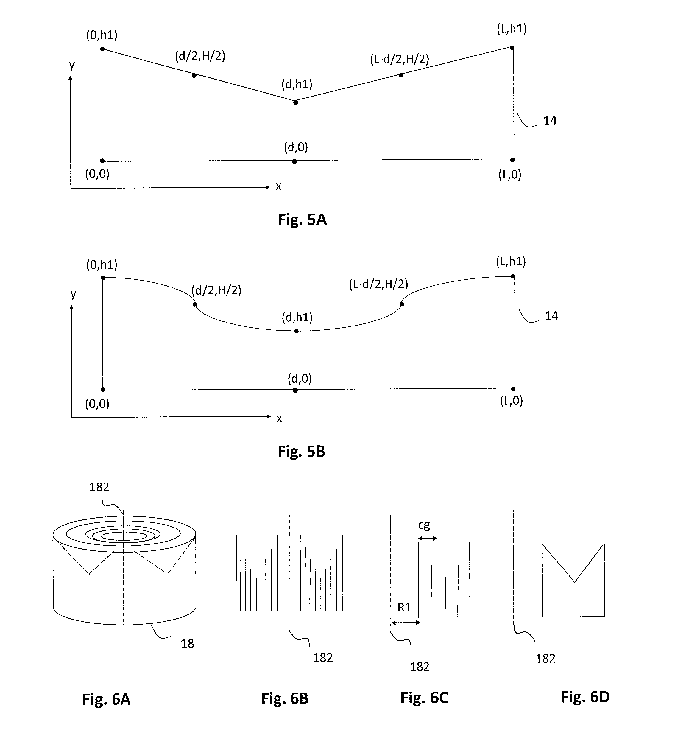
[0185]In a first example, a conventional double pancake coil made of 50 turns of superconducting tapes with inner radius of 5 cm was optimized by varying the local critical current. The coil was optimized by using a pair of “M-shaped” coils in a front to front array arrangement. The table below summarized the parameters of the original (conventional) coil and the optimized coil.
Optimized coil using front-to-frontOriginal (Conventional) coil“M-shape” coils arrangementIC(DC) = 65.11 A,IC(DC) = 79.24 A,central |B| = 0.118 Tcentral |B| = 0.141 TIC(AC) = 71 AIC(AC) = 85 AAC losses at 71 A ---> 0.3047AC losses at 71 A ---> 0.2202J / cycleJ / cycleAC losses at 77.12 A ---> 0.3013J / cycleAC losses at 85 A ---> 0.4419J / cycle
[0186]FIG. 19 shows the magnetic field (in Tesla) for the original coils (FIG. 19A) constituting the double pancake coil and the “M-shaped” coils (FIG. 19B) at their respective critical currents Ic(DC). Both configurations use the same amount of superconducting (HTS) tape. The...
example 2
[0189]In a second example, a striated tape having 10 filaments was optimized. FIG. 21 shows simulation results for a non-optimized 4 mm wide tape having 10 filaments of equal width (FIGS. 21A and 21C) and for an optimized 4 mm wide tape having 10 filaments with a wider outer filament (FIGS. 21B and 21D).
[0190]FIG. 21A to 21B[[a-b]] show the magnetic flux lines at peak value across the tape. A perpendicular magnetic flux density of 10 mT at 50 Hz is applied to both tapes. It is easy to note that in the optimized tape (FIG. 21B), the magnetic flux density in the gaps is lower than in the non-optimized tape (FIG. 21A). As discussed in detail above, this effect allows for reduced AC losses in the overall tape. Thus in the non-optimized tape the AC losses at 10 mT and 50 Hz are about 106.5 μJ / cycle, whereas in the case of optimized tape the AC losses at 10 mT and 50 Hz are about 97.6 μJ / cycle. Accordingly, in the optimized tape shown in FIG. 21B, it is possible to achieve about 8% reduct...
example 3
[0192]As explained above, reduction of the critical current density Jc, due for example to the magnetic field, may be compensated with superconducting material or temperature optimization. In an example, a larger amount of superconducting material may be allocated in the regions where Jc is lower and this may be compensated by allowing a smaller amount of superconducting material in the region where Jc is higher. Alternatively or in addition, heat sinks may be located where Jc is lower. These techniques can also be used for round wires.
[0193]In a third example, a coil is mass-optimized by using round wires having two different calibers. FIG. 22 shows simulation results of the magnetic field (in Tesla) of an original coil (FIG. 22A) and optimized coil (FIG. 22B) at their respective critical currents Ic(DC). In both cases the coil is made of NbTi and has a 5 cm inner radius and 160 turns.
[0194]The original coil is formed by a wire having constant diameter of 0.99 mm having cross-secti...
PUM
 Abstract
Description
Claims
Application Information
 - R&D
- Intellectual Property
- Life Sciences
- Materials
- Tech Scout
- Unparalleled Data Quality
- Higher Quality Content
- 60% Fewer Hallucinations
Browse by: Latest US Patents, China's latest patents, Technical Efficacy Thesaurus, Application Domain, Technology Topic, Popular Technical Reports.
© 2025 PatSnap. All rights reserved.Legal|Privacy policy|Modern Slavery Act Transparency Statement|Sitemap|About US| Contact US: help@patsnap.com


