Cage for a bearing assembly and manufacturing method

Active Publication Date: 2016-02-11
AB SKF
View PDF9 Cites 1 Cited by
  • Summary
  • Abstract
  • Description
  • Claims
  • Application Information

AI Technical Summary

Benefits of technology

The present invention is about a new way to make an annular-shaped cage for use in rolling bearings. The new method makes the cage easier to handle and manufacture, and allows for high production rates and low material costs. The cage can be made from a thin and light material, which reduces its moments of inertia and makes it more efficient. The U-shaped cross section also allows for better holding and storing of lubricant, which improves the performance of the bearing and reduces the need for maintenance. By using a thinner workpiece and forming windows in the workpiece, a rib-like structure is obtained, which minimizes the need for additional assembly steps and costs. The use of a one-piece sheet material also reduces manufacturing steps and avoids unfavourable joints. Overall, the invention provides a faster, more cost-effective way to make annular-shaped cages for rolling bearings.

Problems solved by technology

The added weight to the bearing assembly from the cage increases the overall weight and moment of inertia of the rotating components of the bearing assembly.
The cage also impedes the performance of the bearing assembly and increases the cost for handling and manufacturing.

Method used


Image

  • Cage for a bearing assembly and manufacturing method
  • Cage for a bearing assembly and manufacturing method
  • Cage for a bearing assembly and manufacturing method

Examples


Embodiment Construction

[0053]The present invention will now be described more fully hereinafter with reference to the accompanying drawings, in which a currently preferred embodiment of the invention is shown. This invention may, however, be embodied in many different forms and should not be construed as limited to the embodiments set forth herein; rather, these embodiments are provided for thoroughness and completeness, and fully convey the scope of the invention to the skilled person. Like reference characters refer to like elements throughout.

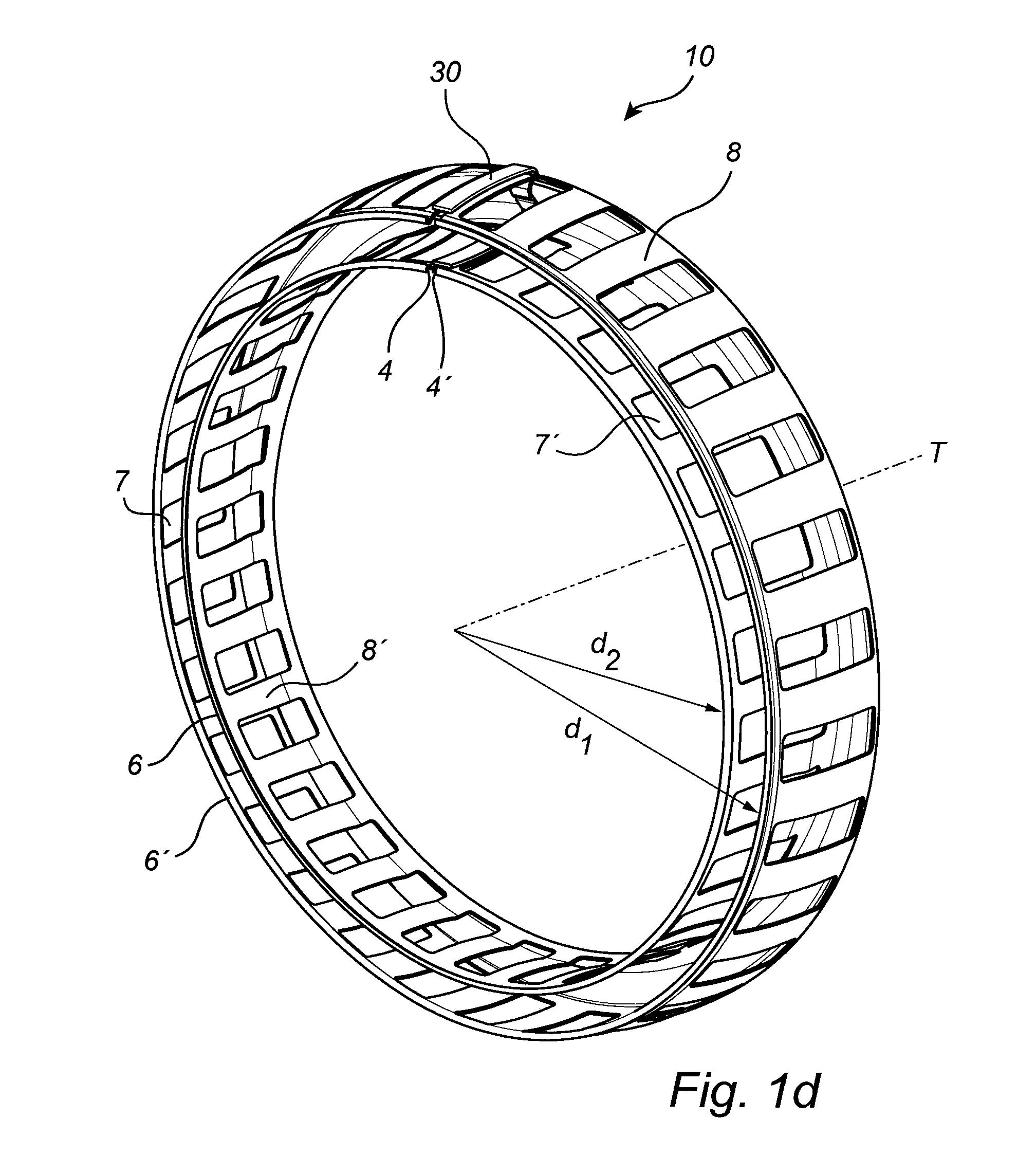
[0054]In the drawings, reference number 10 generally denotes an annular-shaped cage which may be manufactured using the method of an embodiment of the present invention. Such an annular-shaped cage is used in a rolling bearing assembly. The annular-shaped cage has a U-shaped cross section. Moreover, the annular-shaped cage is provided with a first set of windows and a second set of windows (7, 7′, 25, 25′, 102, 102′) for receiving and positioning a set of rolling ...


PUM

PropertyMeasurementUnit
Flow rateaaaaaaaaaa

Abstract

A method for producing an annular-shaped cage for a rolling bearing assembly. The method comprises steps of: (a) providing a workpiece contained in a plane having a first side and a second side; (b) forming an annular-shaped cage from the workpiece, the annular-shaped cage having a U-shaped cross section such that portions of the first side of the workpiece face each other; and (c) forming a plurality of windows in the workpiece for receiving and positioning a set of rolling elements.

Description

CROSS REFERENCE TO RELATED APPLICATION[0001]This is a United States National Stage Application claiming the benefit of International Application Number PCT / SE2014 / 000034 filed on 3 Apr. 2014 (03.04.2014), which claims the benefit of Sweden (SE) Patent Application Number 1300244-9, both of which are incorporated herein by reference in their entireties.FIELD OF THE INVENTION[0002]The present invention relates to a method for producing a cage for a rolling bearing assembly. In addition, the present invention relates to a cage for a rolling bearing assembly. Moreover, the present invention relates to a cage assembly for a rolling bearing assembly.[0003]The cage may for example be used for controlling a position of a set of rolling elements in a roller bearing assembly or ball bearing assembly, or equivalent. The rolling elements may either be controlled in relation to each other and / or in relation to the raceways of the rolling bearing assembly.BACKGROUND OF THE INVENTION[0004]In the fi...

Claims


Application Information

Patent Timeline
IPC IPC(8): F16C33/54F16C33/48
CPCF16C33/545F16C33/485F16C33/547B21D53/12F16C23/086F16C33/4658F16C33/542F16C33/7893F16C19/38F16C33/422F16C33/427
Inventor LINDEN, HANS
Owner AB SKF
Why Eureka
Try Eureka