Orientating apparatus

Inactive Publication Date: 2008-01-24
EASTMAN KODAK CO
View PDF11 Cites 1 Cited by
  • Summary
  • Abstract
  • Description
  • Claims
  • Application Information

AI Technical Summary

Benefits of technology

[0007]In accordance with an object of the invention, both a system and a method are provided for improving the manufacturing of inkjet ink tanks, and specifically the efficient and accurate wick placement into an ink tank during manufacturing.

Problems solved by technology

A common problem in manufacturing is the need to assemble one or more components in a preferred orientation into specific location(s) on the final assembled device.
Vibratory bowl feeders are typically expensive and have a large footprint.

Method used


Image

  • Orientating apparatus
  • Orientating apparatus
  • Orientating apparatus

Examples


Embodiment Construction

[0017]The present description will be directed in particular to elements forming part of, or cooperating more directly with, apparatus and methods in accordance with the present invention. It is to be understood that elements not specifically shown or described may take various forms well known to those skilled in the art.

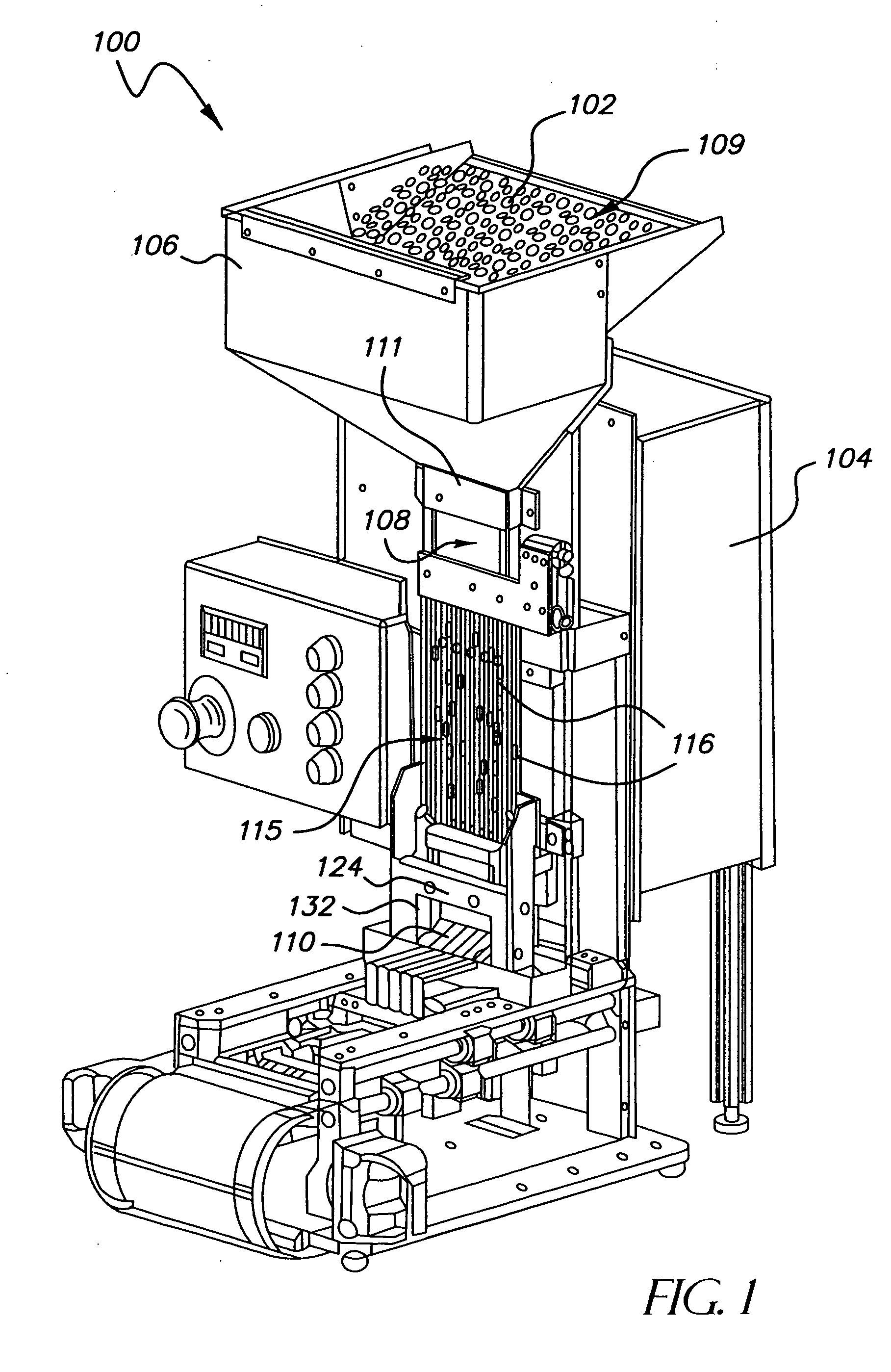
[0018]FIG. 1 shows an apparatus 100, also referred to as the orientating apparatus, for orientating components 102 of an ink tank during assembly. A frame 104 preferably supports the orientating apparatus 100 including a component source, such as a hopper 106, to contain the components, which can be transported to the hopper in a variety of ways including a conveyer system (not shown). Hopper 106 may optionally have a cover 109 to prevent external contaminants from landing on the components, and also to keep components 102 from bouncing out of the top of the hopper. Components 102 have somewhat random orientation in hopper 106. The orientating apparatus 100 orients...


PUM


Abstract

An orientating apparatus and associated method includes an agitator, one or more channels adjacent the agitator, and a lower component delivery portion. The agitator is powered by a drive assembly, which induces a motions in relation to the channels. The channels are designed such that a component for orienting can only pass through the channels in a preferred orientation, and the agitator provides opportunities for the components to achieve proper orientation to enter the channels. This allows the components to pass through the channels to the staging portion in an orientated manner. This orientating apparatus, intended for the automatic positioning of wicks, will work on manufacturing lines with any number of apparatus or parts, as long as it is generally adjacent the utilization point.

Description

FIELD OF THE INVENTION[0001]The invention relates generally to the field of manufacturing, such as inkjet ink tank manufacturing, and more particularly to an orientating apparatus intended for the automatic positioning of parts, which nominally are all of the same size.BACKGROUND OF THE INVENTION[0002]A common problem in manufacturing is the need to assemble one or more components in a preferred orientation into specific location(s) on the final assembled device. Such components may have some degree of symmetry, but are less symmetric than a sphere. Typically the components are supplied as a batch of nonoriented parts. Of course, it is possible for such parts to be manually oriented and assembled into the final device, but in order to achieve faster assembly throughput and lower cost, some means of automatic orientation and positioning is desirable.[0003]A commonly used apparatus for selecting parts out of a batch is the vibratory bowl feeder. The vibratory bowl feeder shakes the ba...

Claims


Application Information

Patent Timeline
IPC IPC(8): B65G47/00
CPCB65G47/145B65G47/086
Inventor CASHIMERE, BRIAN J.WALTER, GERALD N.
Owner EASTMAN KODAK CO
Why Eureka
Try Eureka