
Lateral-flow assay device with filtration flow control

a technology of lateral flow and assay device, which is applied in the field of clinical diagnostics, can solve problems such as unsatisfactory lower sensitivity, and achieve the effects of improving filtration efficiency and plasma yield, fast and reliable flow, and better control of filtration ra

Active Publication Date: 2016-02-11
ORTHO-CLINICAL DIAGNOSTICS
View PDF1 Cites 13 Cited by
  • Summary
  • Abstract
  • Description
  • Claims
  • Application Information

AI Technical Summary

Benefits of technology

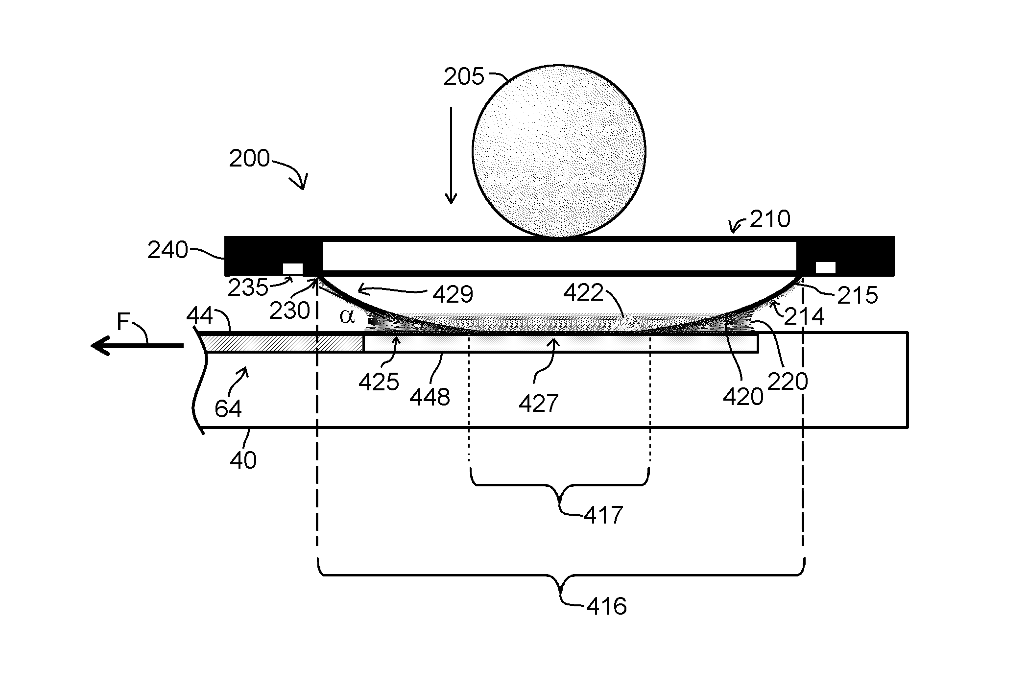
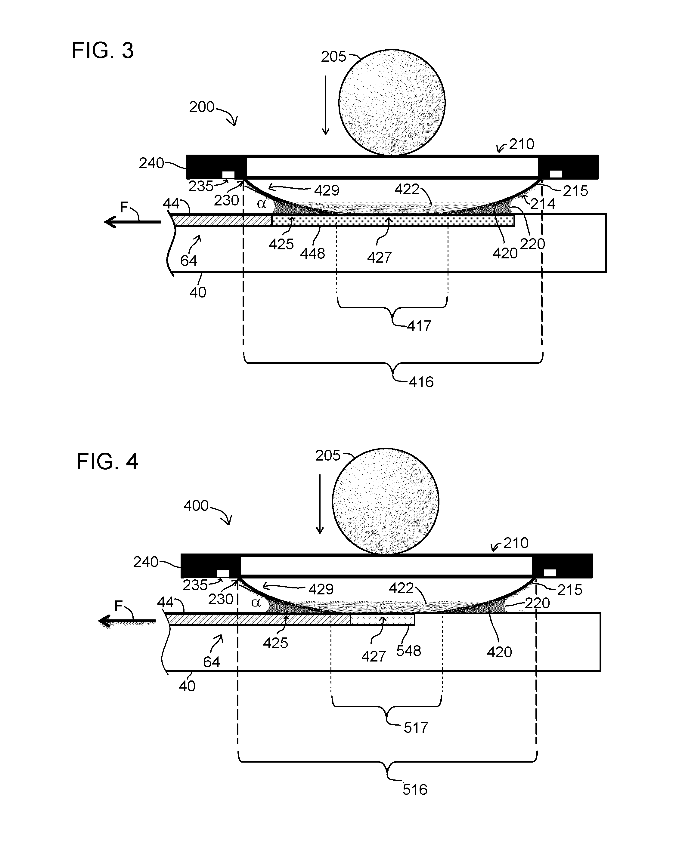
The present invention provides a lateral-flow assay device that can improve the yield of fluid being tested, allowing for the use of smaller sample volumes. By designing the sample addition zone, the contact area of the sample, and the geometry of the filter for a given sample size, the device can provide better control over filtration rate and reduce the chance of fluid reaching at or even beyond the supported edge of the filter. This results in faster and more reliable flow of the applied sample to the device, due to better control of capillary pressure. Additionally, the device can improve filtration efficiency and plasma yield, resulting in a significantly higher plasma yield as compared to other known assay device designs. The device also provides a stable fluid supply for the channel flow through the various zones of the lateral-flow assay device, regardless of sample hematocrit level or sample volume. The size of the meniscus may differ, but its capillary pressure remains small compared to a capillary pressure in the flow channel or the wicking zone, resulting in a generally constant flow rate during fluid flow.

Problems solved by technology

For many assays, however, small sample volume leads to undesirable lower sensitivity.

Method used


Image

  • Lateral-flow assay device with filtration flow control
  • Lateral-flow assay device with filtration flow control
  • Lateral-flow assay device with filtration flow control

Examples


Embodiment Construction

[0030]The following description relates to certain embodiments for a filter design for a lateral-flow assay device. It will be readily apparent that the embodiments described herein are intended to be merely exemplary and therefore numerous other variations and modifications are possible. In addition, several terms are used throughout the following discussion such as “first”, “second”, “above”, “below”, “top”, “bottom”, “lateral” and the like for purposes of providing a suitable frame of reference in regard to the accompanying drawings. To that end, these terms should not be regarded as being overly restrictive in terms of the scope of the described apparatus and methods, unless otherwise specifically indicated herein.

[0031]It should further be noted that the accompanying drawings are not necessarily presented to scale and therefore no narrowing interpretation should be made in terms of dimensions that have been depicted.

[0032]As used in this specification and the appended claims, t...


PUM


Abstract

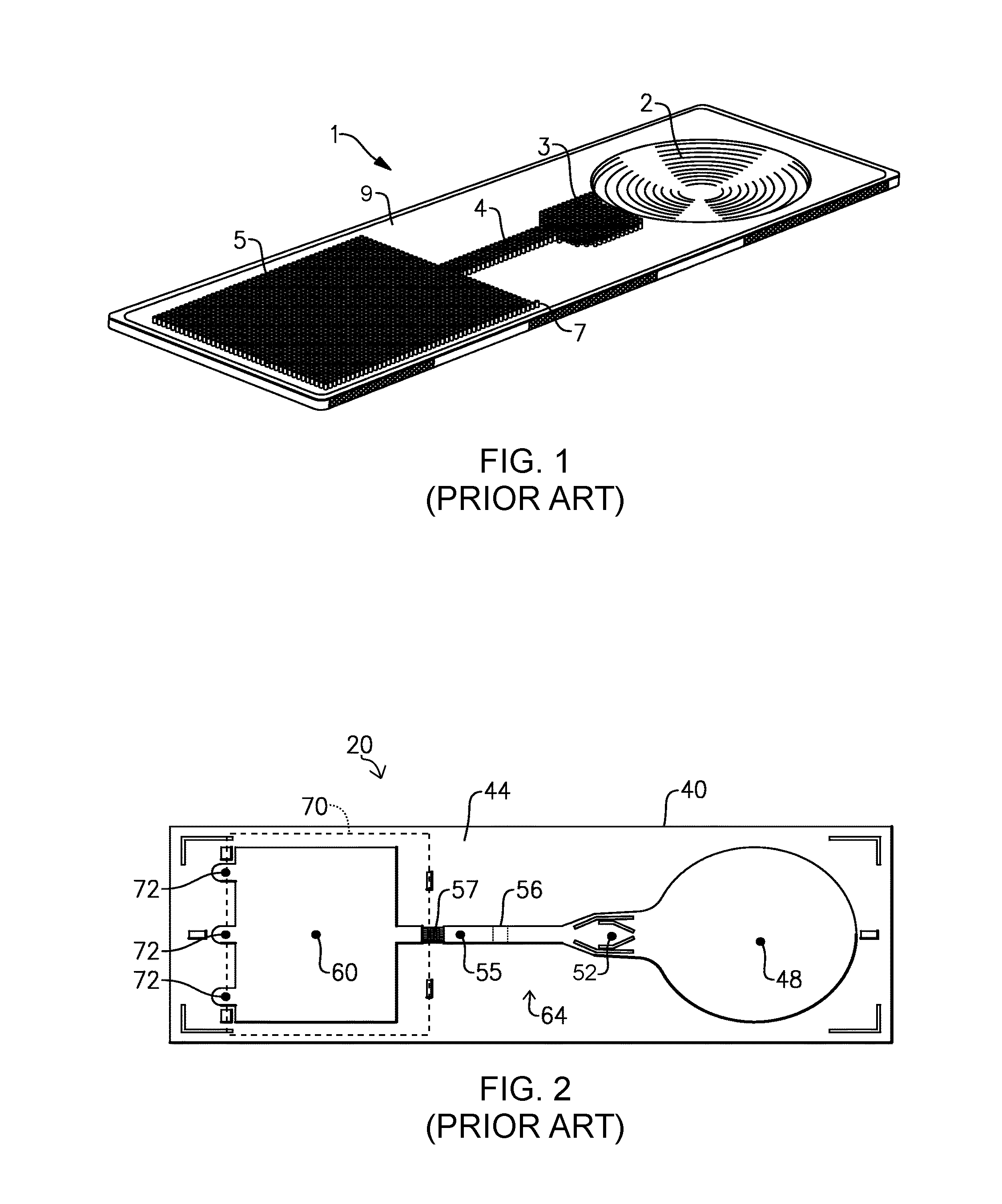
A lateral-flow assay device includes a substrate with a sample addition zone and a fluid flow path. A cover supports a filter having a portion contacting the substrate to create a contact area that at least partly overlaps the sample addition zone. Another portion extends from the contact portion to the supported periphery of the filter to define with the substrate a reservoir configured to retain the filtrate by capillary pressure between the substrate and the extending portion. The reservoir volume is based on an acute angle formed between the substrate and the extending portion of the filter and on a fluid meniscus of the filtrate. The filter and sample addition zone are configured to provide capillary pressure drawing the filtrate from the reservoir to the sample addition zone. Methods for controlling flow characteristics in a lateral-flow assay device are also described.

Description

CROSS REFERENCE TO RELATED APPLICATION(S)[0001]This application claims priority under applicable portions of 35 U.S.C. §119 to U.S. Patent Application Ser. No. 62 / 034,830, filed Aug. 8, 2014, and entitled: LATERAL-FLOW ASSAY DEVICE WITH FILTRATION FLOW CONTROL, the entire contents of which are incorporated by reference herein.TECHNICAL FIELD[0002]This application relates to the field of clinical diagnostics and more specifically to a lateral-flow assay device.BACKGROUND[0003]The use of diagnostic assays is very well known for the diagnosis, treatment and management of many diseases. In that regard, different types of diagnostic assays have been developed to simplify the detection of various analytes in clinical samples such as blood, serum, plasma, urine, saliva, tissue biopsies, stool, sputum, skin or throat swabs and tissue samples or processed tissue samples. These assays are frequently expected to provide a fast and reliable result, while being easy to use and inexpensive to man...

Claims


Application Information

Patent Timeline
Patent Type & Authority Applications(United States)
IPC IPC(8): B01L3/00
CPCB01L3/5023B01L2300/0681B01L2400/0406G01N33/558G01N33/54388
Inventor DING, ZHONGSCALICE, EDWARD R.HOSIMER, PHILIP C.
Owner ORTHO-CLINICAL DIAGNOSTICS
Learn More