
Systems and methods for spectrally dispersed illumination optical coherence tomography

a technology spectrally dispersed illumination, applied in the field of optical coherence tomography, can solve the problems of general inability to use other non-confocal parallel techniques, and achieve the effects of sacrificing sensitivity, safe illumination of tissue, and more power

Active Publication Date: 2016-01-07
CARL ZEISS MEDITEC INC
View PDF0 Cites 16 Cited by
  • Summary
  • Abstract
  • Description
  • Claims
  • Application Information

AI Technical Summary

Benefits of technology

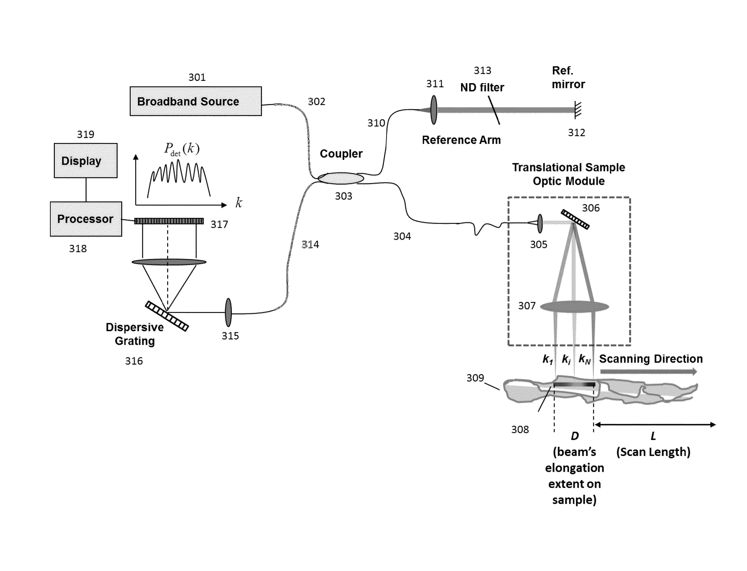
The present patent describes a method for obtaining high-speed OCT data without sacrificing sensitivity. This is achieved through the use of parallel OCT and spectrally dispersed illumination OCT. The broadband light from the source is distributed in the form of a spectrum onto the sample, and each acquisition simultaneously provides spectral interference information from multiple locations in the sample. This method has the advantage of line field OCT, to be able to illuminate multiple locations in the tissue simultaneously, while still being able to maintain high confocality, minimizing the image degradation effects of multiple scattering. The confocality of the spectrally dispersed illumination OCT system is maintained, because the sample light can be coupled into a single mode fiber, which would serve as a pinhole. This method can operate at higher illumination powers, because dispersing the light onto a larger area on the sample increases the total maximum permissible exposure.

Problems solved by technology

This is in general not possible with other non-confocal parallel techniques, such as full field OCT.

Method used


Image

  • Systems and methods for spectrally dispersed illumination optical coherence tomography
  • Systems and methods for spectrally dispersed illumination optical coherence tomography
  • Systems and methods for spectrally dispersed illumination optical coherence tomography

Examples


Embodiment Construction

[0021]A basic concept of the present application is to spectrally disperse or de-multiplex illumination of the incident light at the sample, move the spectrally dispersed light along the spatial direction of dispersion and spectrally resolve the detection of the light interference. The broadband light from the source is distributed spectrally on the sample, and each acquisition simultaneously provides partial spectral interference information from multiple locations in the sample. Thus for a given spatial point, a single observation will be of a partial spectrum A-scan. When multiple partial spectrum A-scan observations are made at the same point by shifting the spectrum of light on to the tissue, the point will be illuminated by the entire broadband spectrum of the light source over time, thereby making it possible to construct a full axial resolution A-scan.

[0022]Spectral spreading of the incident beam on a sample makes it possible to increase incident power within safe limits. He...


PUM


Abstract

Systems and methods are presented for acquisition and processing of spectrally dispersed illumination optical coherence tomographic data. Light from a source is distributed spectrally on the sample, and each acquisition simultaneously provides partial spectral interference information from multiple locations in the sample. Thus for a given spatial point, a single observation will be of a partial spectrum A-scan. When multiple partial spectrum A-scan observations are made at the same point by shifting the spectrum of light on to the tissue, the point can be observed by the entire broadband spectrum of the light source, thereby making it possible to create a full axial resolution A-scan.

Description

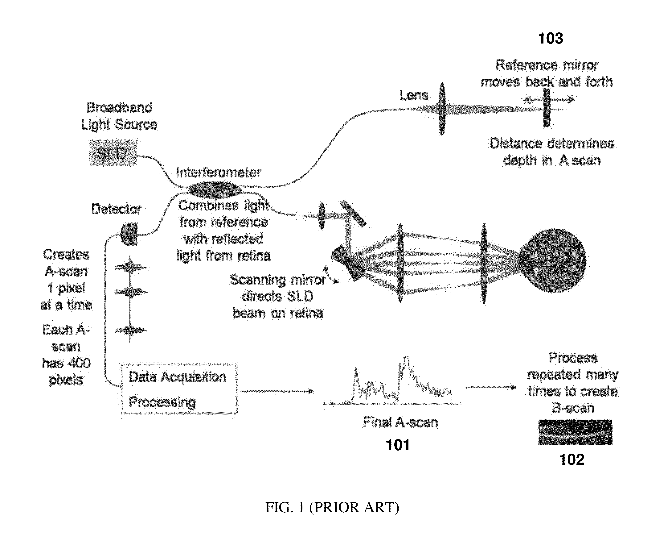
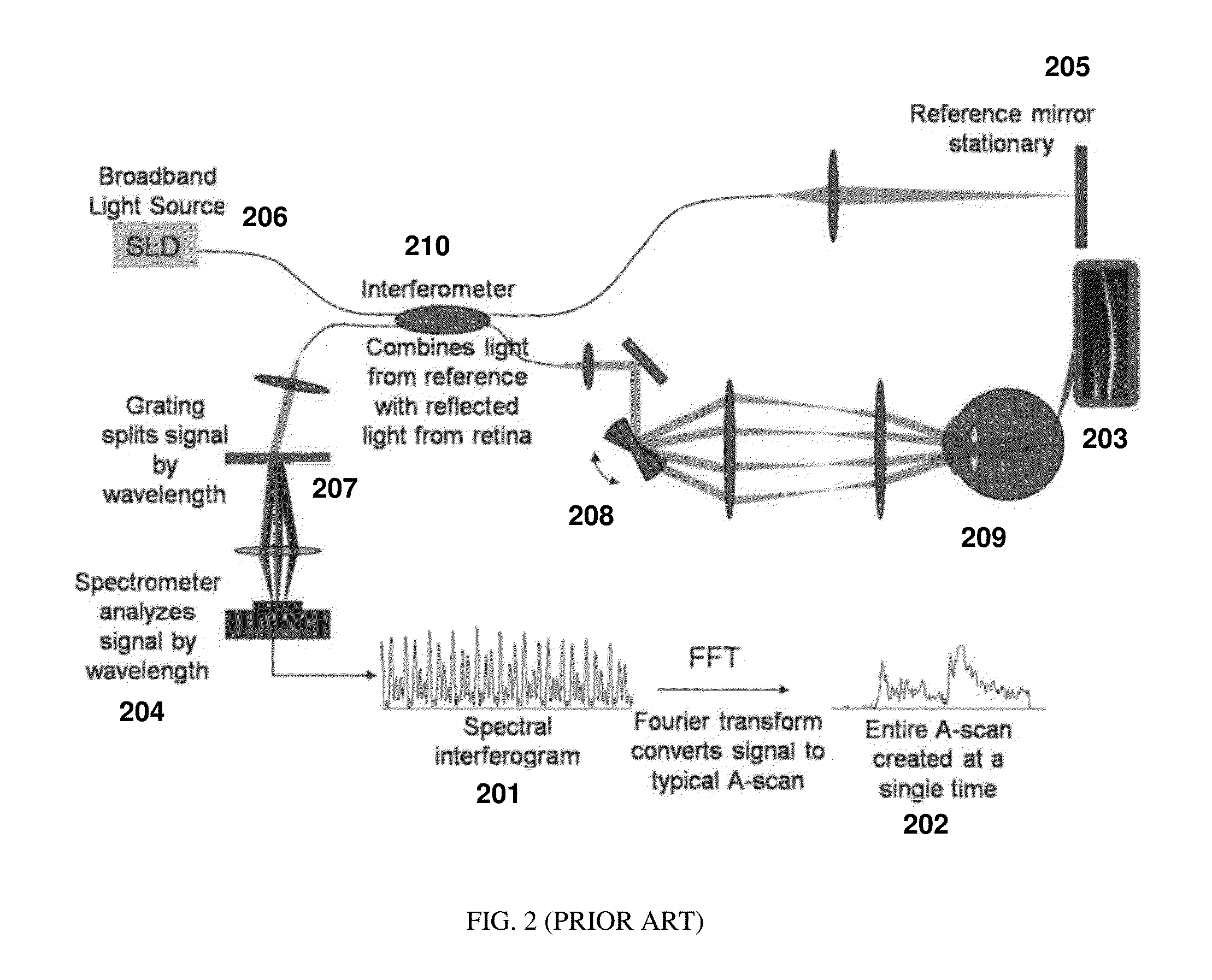
PRIORITY[0001]The present application claims priority to U.S. Provisional Application Ser. No. 62 / 020,556 filed Jul. 3, 2014 the contents of which are hereby incorporated by reference.TECHNICAL FIELD[0002]The present application relates to the field of optical coherence tomography. In particular, the present application describes embodiments related to producing and processing partial spectrum A-scans with optical coherence tomographic instrumentation.BACKGROUND[0003]Optical Coherence Tomography (OCT) is an interferometric technique that can provide images of samples including tissue structure on the micrometer scale in situ and in real time (Huang, D. et al., Science 254, 1178-81, 1991). OCT is based on the principle of low coherence interferometry (LCI) and determines the scattering profile of a sample along the OCT beam by detecting the interference of light reflected from a sample and a reference beam (Fercher, A. F. et al., Opt. Lett. 13, 186, 1988). Each scattering profile in ...

Claims


Application Information

Patent Timeline
Patent Type & Authority Applications(United States)
IPC IPC(8): A61B3/10A61B3/00A61B3/14G01J3/28G01J3/45
CPCA61B3/102A61B3/14G01J3/2823G01J3/45A61B3/0025G01B9/02044G01B9/02091
Inventor SHARMA, UTKARSHSCHMOLL, TILMANWEI, XING
Owner CARL ZEISS MEDITEC INC
Learn More