Methods for analyzing and compressing multiple images

Inactive Publication Date: 2015-12-24
KORB ANDREW ROBERT +1
View PDF0 Cites 118 Cited by
  • Summary
  • Abstract
  • Description
  • Claims
  • Application Information

AI Technical Summary

Benefits of technology

The present patent provides various methods for improving image processing, analysis, and compression by combining images and comparing them to a georeferenced scene topography. This allows for improved accuracy, resolution, and signal-to-noise ratio. By rigorously analyzing the differences between images and identifying significant changes, data compression can be achieved and information about the surface orientation, three-dimensional information about adjacent surfaces, and background surface properties can be accurately estimated. Additionally, the patent describes novel techniques for identifying surface materials using the bi-directional scatter distribution function (BSDF) or BRDF functions, which are described to perform supervised and unsupervised classification using empirical measurements.

Problems solved by technology

As a result of error in known surface attitude, the difference between true orientation and horizontal, there are large uncertainties and errors in measured bidirectional reflectance distribution function (BRDF) reflectivity and emissivity, resulting from attitude-knowledge-error.
Further, some remote sensing problems, such as characterizing material identification and temperature / emissivity, are fundamentally under-determined, e.g., have more unknowns than measurements, which require additional constraints or a priori knowledge, which reduces or limits accuracy obtained from a single image or measurement.
As a result, change detection is limited by poor knowledge of surface orientations.
Mundy et al. use a Gaussian mixture model that fundamentally limits the accuracy of spectroradiometric exploitation, because the radiometry does not conform to either a Lambertian model or a BRDF-formulation reflectivity model as proposed by Hapke or others.

Method used


Image

  • Methods for analyzing and compressing multiple images
  • Methods for analyzing and compressing multiple images
  • Methods for analyzing and compressing multiple images

Examples


Embodiment Construction

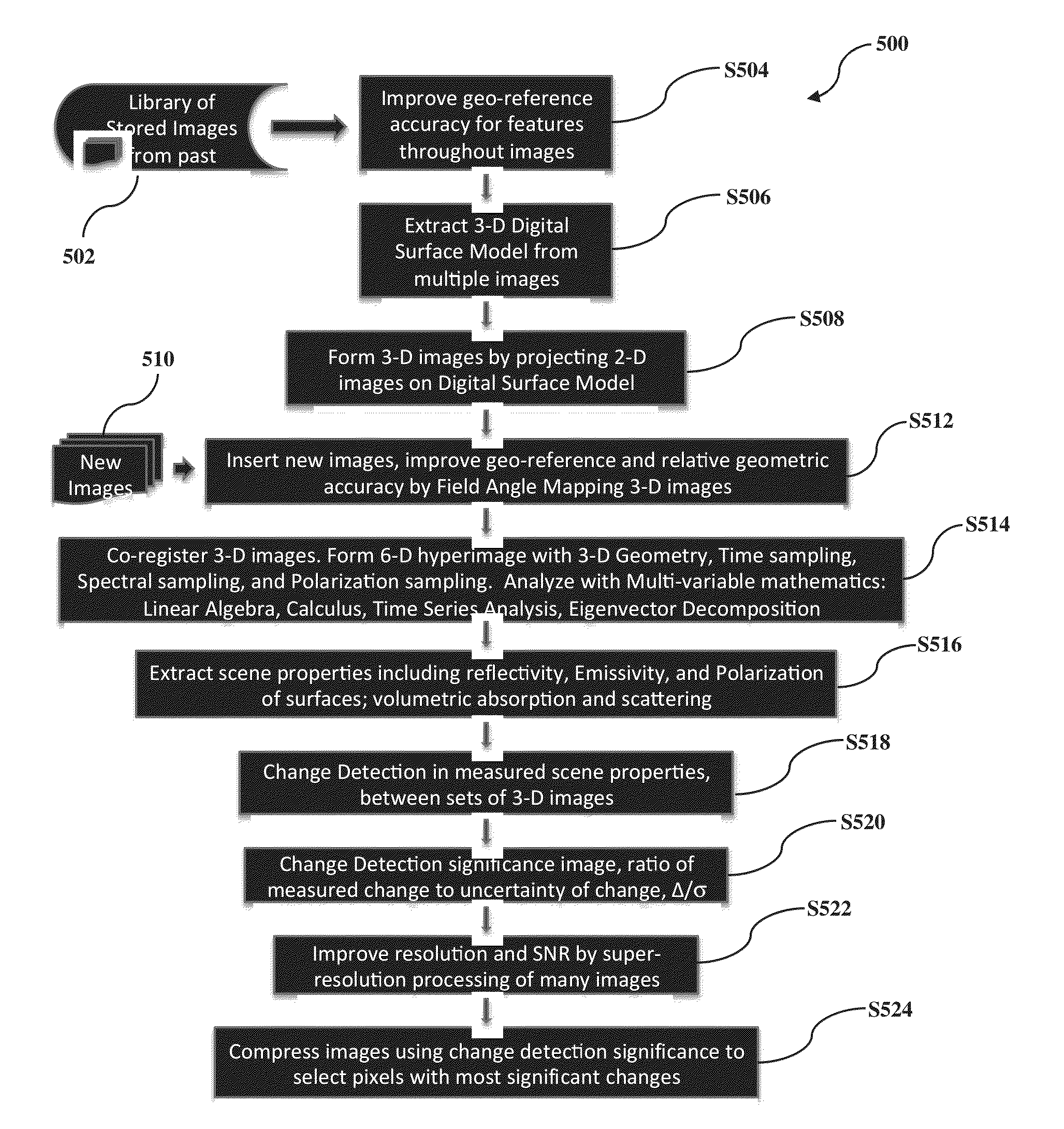
[0067]The present disclosure, through one or more of its various aspects, embodiments and / or specific features or sub-components, is thus intended to bring out one or more of the advantages as specifically described below.

[0068]The present application may be used with an onboard spacecraft or aircraft data processing system. In this regard, the onboard spacecraft or aircraft data processing system may improve accuracy, resolution, and reduce the communication rate between satellites and ground systems by co-registering and analyzing images onboard the spacecraft. The spacecraft or aircraft data processing system may locate image regions with significant change or significant queried information for prioritized transmission, processing, and storage. In regions without significant change, information from multiple images can be co-added to increase signal-to-noise ratio while minimizing communication rate.

[0069]The present application may also be used with an automated aircraft and sa...


PUM


Abstract

A multi-temporal, multi-angle, automated target exploitation method is provided for processing a large number of images. The system geo-rectifies the images to a three-dimensional surface topography, co-registers groups of the images with fractional pixel accuracy, automates change detection, evaluates the significance of change between the images, and massively compresses imagery sets based on the statistical significance of change. The method improves the resolution, accuracy, and quality of information extracted beyond the capabilities of any single image, and creates registered six-dimensional image datasets appropriate for mathematical treatment using standard multi-variable analysis techniques from vector calculus and linear algebra such as time-series analysis and eigenvector decomposition.

Description

CROSS-REFERENCE TO RELATED APPLICATIONS[0001]The present application claims the benefit of U.S. Provisional Pat. Appl. No. 61 / 757,892, filed on Jan. 29, 2013, the disclosure of which, including the specification and figures, is incorporated herein by reference in its entirety.[0002]The present application is related to the disclosures of: U.S. Provisional Pat. Appl. No. 61 / 153,934; U.S. patent application Ser. No. 12 / 708,482, now U.S. Pat. No. 8,238,903; U.S. patent application Ser. No. 13 / 544,141, now U.S. Pat. No. 8,480,036; and U.S. patent application Ser. No. 13 / 544,155, now U.S. Pat. No. 8,360,367. The disclosures of all of these documents, including the specifications and figures, are incorporated herein by reference in their entireties.BACKGROUND[0003]1. Field of the Disclosure[0004]The present disclose generally relates to the field of orthorectification. More particularly, the present disclosure relates to various systems, methods, and media for performing sensor model refi...

Claims


Application Information

Patent Timeline
IPC IPC(8): G06T15/20G06T17/05H04N19/136G06K9/46G06K9/52G06K9/62G06K9/00G06T7/00G06V10/60
CPCG06T9/00G06T7/75G06T17/05G06K9/46G06K9/6298G06K9/6215G06K9/52G06K9/00476H04N19/136G06T15/20G06T2207/10032G06T2207/30181G06T2207/30244G06T7/33G06T7/73G06T2210/56G06V20/647G06V30/422G06V20/176G06V10/60G06V2201/12G06F18/22
Inventor KORB, ANDREW ROBERTKORB, CHARLES LAURENCE
Owner KORB ANDREW ROBERT
Why Eureka
Try Eureka