Pumped-Storage Power Plant

a power plant and pumped storage technology, applied in photovoltaics, motors, energy industry, etc., can solve the problems of high storage loss, high cost, and inability to economically use on a large scale, and achieve the effect of reducing the mass of the storage reservoir, reducing the mass of the pressure vessel and/or the base body, and reducing the potential

Active Publication Date: 2015-12-17
ROENTDEK HANDELS
View PDF3 Cites 13 Cited by
  • Summary
  • Abstract
  • Description
  • Claims
  • Application Information

AI Technical Summary

Benefits of technology

[0053]According to a preferred embodiment of the present disclosure, the pressure vessel has an additional water storage area, not used for energy storage during normal operation, that can be pumped empty in order to reduce the mass of the storage reservoir such that it can be brought up from the ocean floor to the ocean surface. This additional water storage area can either be created by the means that the main cavity is not pumped entirely empty in normal operation, or else one or more separate hollow spaces may be present for this purpose, perhaps in the vessel wall. In this way, the mass of the pressure vessel and/or of the base body can be reduced sufficiently by pumping the additional water storage area empty that the pressure vessel floats on its own, or at least can be brought up with a cable. The pressure vessel that constitutes the water storage volume with the lower potential energy can accordingly be sunk to the ocean floor and brought back to the surface of the water. Thus

Problems solved by technology

An industrial society can only use wind power as a reliable energy source if it is continuously available, however.
Traditional direct storage devices for electricity, such as rechargeable batteries, are only able to store relatively small quantities of energy, have high storage losses, and are also very expensive and thus not economically usable on a large scale.
The currently much-discussed chemical storage methods (e.g., electrolysis of water) and compressed air storage have a relatively poor efficiency in the recovery of the energy thus stored because of the heat losses alone.
However, the demand for such pumped storage power plants exceeds the potential capacity

Method used


Image

  • Pumped-Storage Power Plant
  • Pumped-Storage Power Plant
  • Pumped-Storage Power Plant

Examples


Embodiment Construction

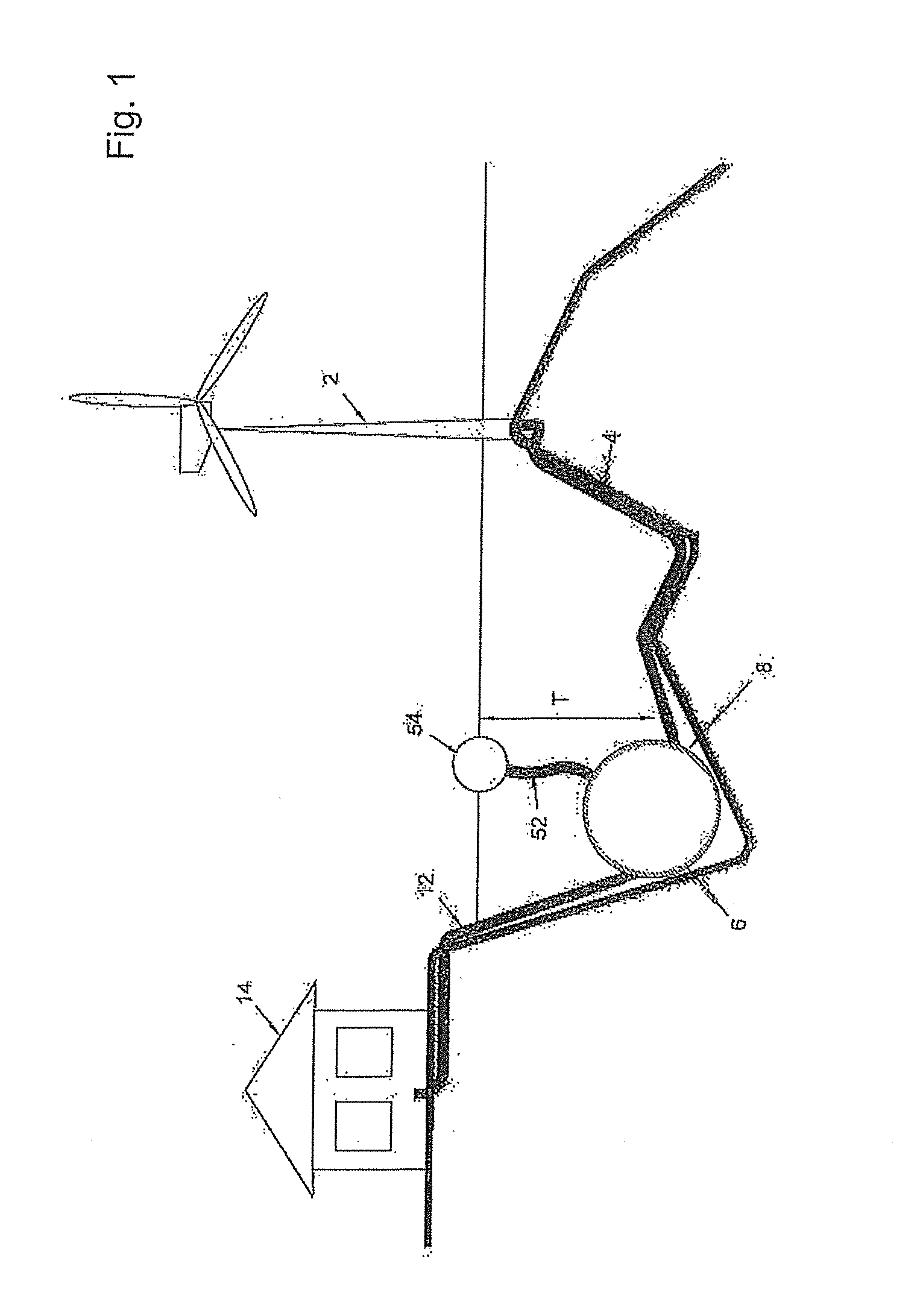
[0079]Referring to FIG. 1, first, the basic structure of the electrical networking of the pumped storage power plant 6 is shown schematically as an overview. Electrical energy is symbolically generated by means of a certain electrical power plant, in this example a wind turbine 2. The wind turbine 2 is connected to the pumped storage power plant 6 by a power line 4 in order to carry the electrical energy from the primary power plant to the pumped storage power plant 6. The pumped storage power plant 6 is located on the ocean floor 8 at a water depth T, which can be a few hundred to a few thousand meters depending on the existing geographic conditions. The pumped storage power plant 6 is also connected to a load 14 by a power line 12 in order to carry the electrical energy from the pumped storage power plant 6 to the load.

[0080]It is evident that the wind turbine 2 shown can representatively stand for a plurality of wind turbines, and that other renewable, fluctuating energy plants s...


PUM


Abstract

An underwater pumped storage power plant that includes: an accumulator system with pressure vessels fillable with water and; a water outlet for water flow out of the system into a surrounding ocean against hydrostatic water pressure (PT) corresponding to water depth (T); a pump at the water outlet to pump water out of the system by converting electrical energy into potential energy corresponding to a displaced water column PT; a water inlet to allow water flow into the system from the surrounding ocean; a common generator at the water inlet, to convert the potential energy back into electrical energy when water flows in; electric lines to transport the electrical energy from the ocean surface to the power plant and back, wherein the pressure vessels are pressure-resistant and resistant to deformation from the PT at the ocean floor.

Description

TECHNICAL FIELD[0001]The present disclosure concerns a pumped storage power plant for temporary reversible storage of energy, such as energy from wind power stations and / or photovoltaic systems with fluctuating availability over time, and also concerns a power supply network having a pumped storage power plant, and a method for reversible temporary storage of electrical energy from primary power plants.BACKGROUND[0002]As a result of the irregular distribution of solar radiation over the surface of the earth, a known temperature distribution arises between the tropics and subtropics on the one hand, and the polar regions on the other hand. This energy gradient is responsible for the known, prevailing large global wind systems, which transport a majority of the radiant energy absorbed by the Earth's surface in the form of wind, to regions including Europe, the Atlantic, the North Sea, etc. in the case of the northern hemisphere.[0003]For many centuries now, mankind has been utilizing ...

Claims


Application Information

Patent Timeline
IPC IPC(8): F03B13/10
CPCF03B13/10F03B3/10F03B13/06F03D9/14Y02E10/20Y02E10/30Y02E10/50Y02E10/72Y02E60/16Y02E70/30Y02P70/50Y02P80/10F03D9/007F03D9/25H02S10/12
Inventor SCHMIDT-BOECKING, HORSTLUTHER, GERHARD
Owner ROENTDEK HANDELS
Why Eureka
Try Eureka