
Battery charger and method of charging a battery

a battery charger and charging system technology, applied in the direction of battery/fuel cell control arrangement, light to electrical conversion, electric devices, etc., can solve the problems of battery or charger damage, user inadvertent selection of wrong type, and failure to charge battery, etc., to achieve fast and convenient charging of such vehicles, safe, efficient and convenient use, and the effect of convenient charging

Inactive Publication Date: 2008-08-12
ARIZONA PUBLIC SERVICE
View PDF2 Cites 100 Cited by
  • Summary
  • Abstract
  • Description
  • Claims
  • Application Information

AI Technical Summary

Benefits of technology

"The present invention provides a charger that can automatically identify the type of battery it is connected to and charge it efficiently. The charger is designed to be compact, lightweight, and safe. It can be used in electric and hybrid vehicles, and is easy to use and maintain. The charger can quickly and conveniently charge electric vehicles while the operator waits. The charger is powered from an external or on-board power source, and includes a transformer and a digital controller to regulate the power level. The charger can also communicate with a digital diagnostic device and is designed to provide a convenient and safe way to charge electric vehicles."

Problems solved by technology

However, this requires a user to select the correct type of battery, and there is a risk that the user may inadvertently select the wrong type.
This could result in a failure to charge the battery and could damage either the battery or the charger.
In addition, in the past, chargers have typically been relatively slow.
But in many applications, this results in the battery, or electric vehicle, for example, being out of operation for a long time while it is being charged.
Furthermore, in the past, many chargers have been bulky and heavy, and a need exists to reduce their size, mass, or both.

Method used


Image

  • Battery charger and method of charging a battery
  • Battery charger and method of charging a battery
  • Battery charger and method of charging a battery

Examples


Embodiment Construction

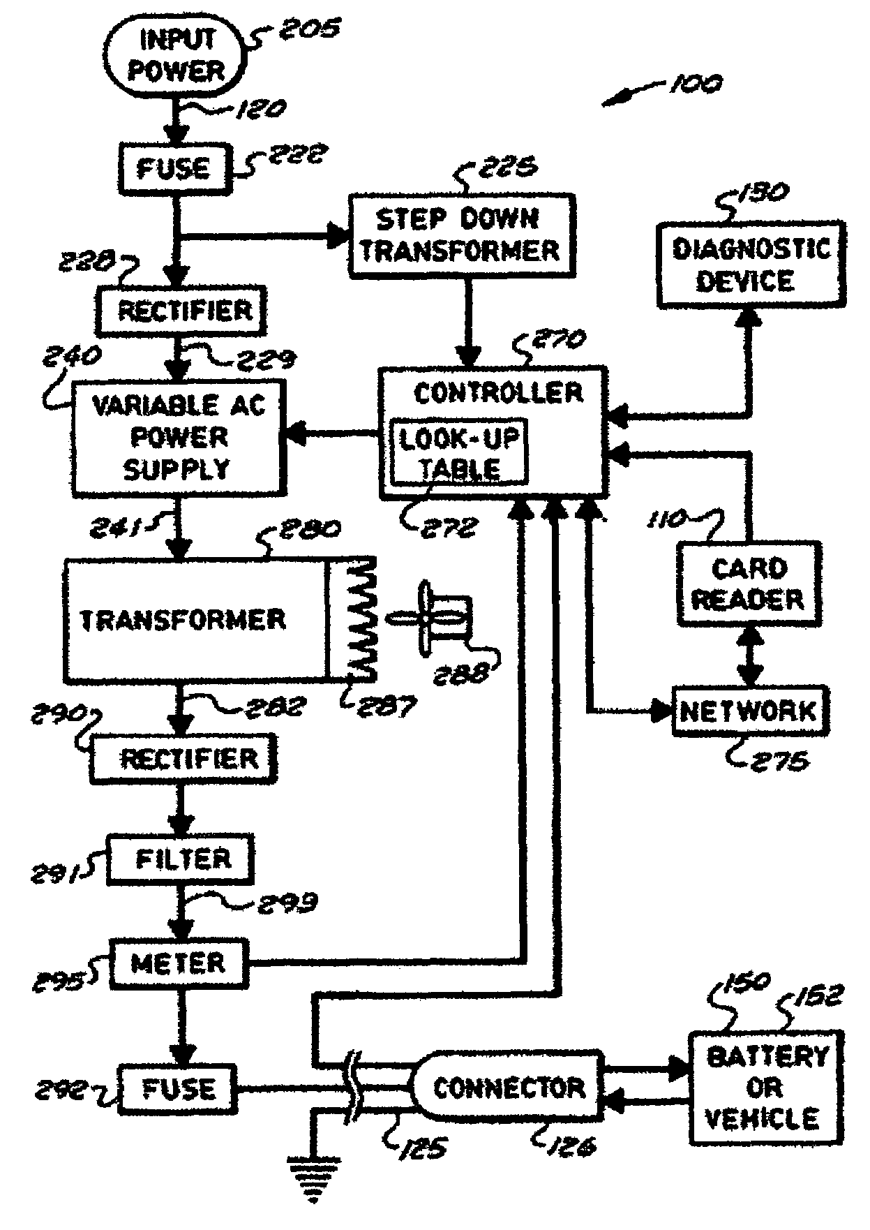
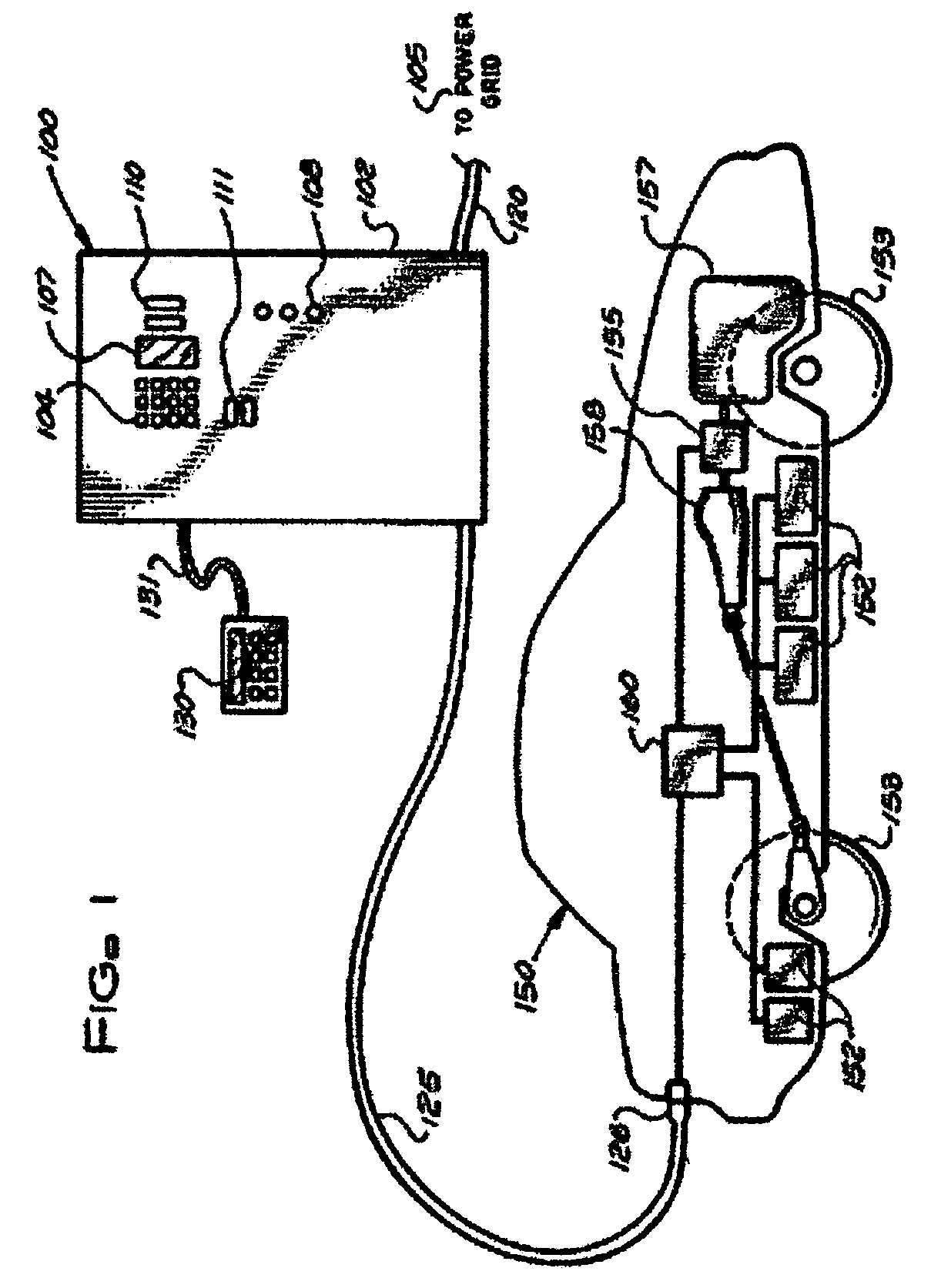
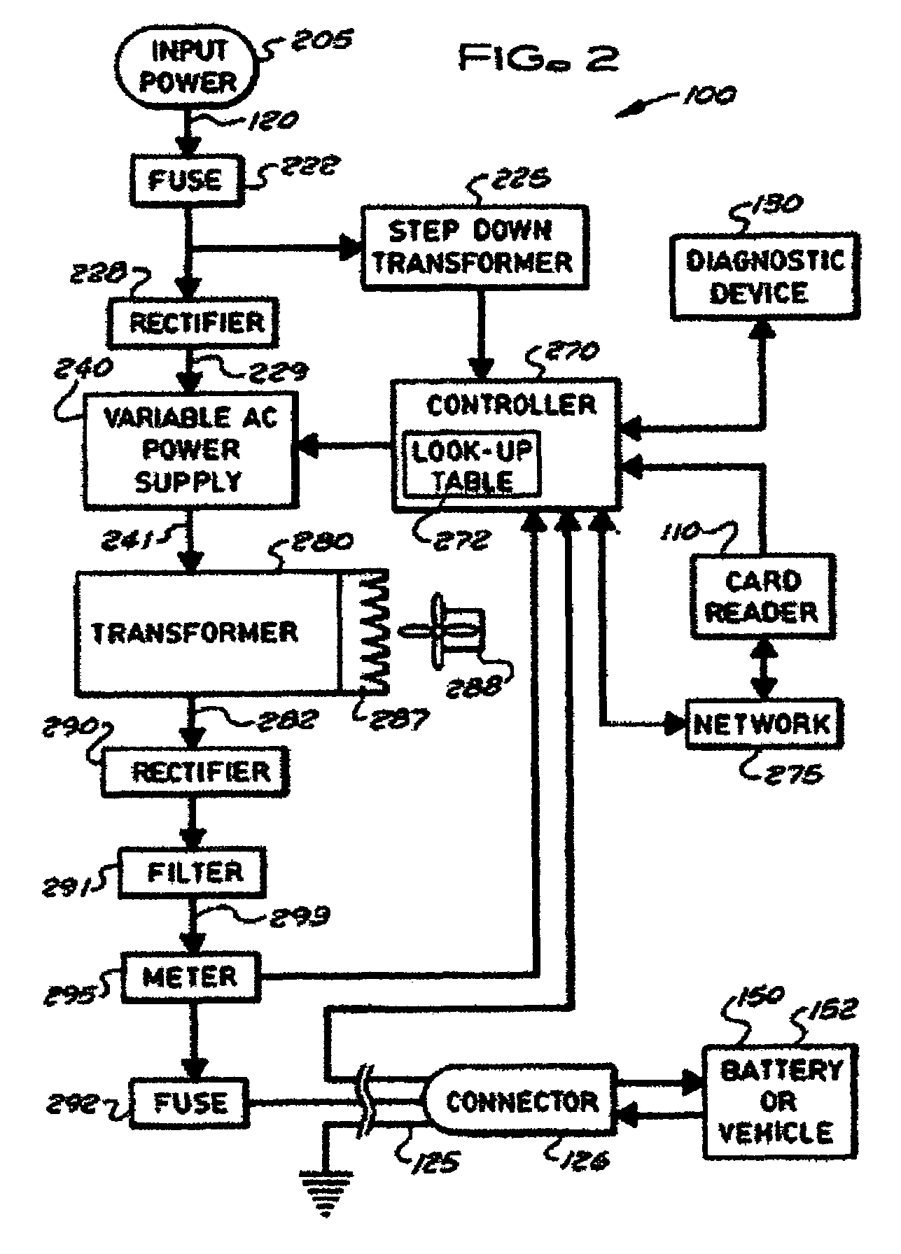
[0026]In general, various embodiments of the present invention include stationary, mobile, and on-board battery chargers, methods of charging batteries, electric-vehicle chargers, and vehicles with chargers, including electric vehicles and hybrid electric vehicles. Chargers in accordance with the present invention may automatically charge at the correct battery voltage for various types of batteries. Chargers in accordance with the present invention generally have variable AC power supplies that are controlled by digital controllers. Chargers generally also have isolation transformers which may change voltage and current, and rectifiers or other switching devices to convert alternating current to direct current. In some embodiments of the present invention, transformers may be foil-type, and may have copper foil, while in other embodiments, transformers may be a wire wound type. Foil transformers may reduce the size and weight (mass) of the charger. Power supplies may be variable-fr...


PUM

PropertyMeasurementUnit
voltageaaaaaaaaaa
voltageaaaaaaaaaa
voltageaaaaaaaaaa

Abstract

Stationary and on-board battery chargers, methods of charging batteries, electric-vehicle chargers, and vehicles with chargers, including electric vehicles and hybrid electric vehicles. Chargers may automatically charge at the correct battery voltage for various types of batteries. Chargers have variable AC power supplies controlled by digital controllers, isolation transformers, and rectifiers. Transformers may be foil-type, and may have copper foil. Power supplies may be variable-frequency generators and the controllers may control the frequency. Use of the variable frequency generator supply facilitates reduced component size and weight and better battery charging performance. Electric vehicle chargers may have card readers, and vehicles may have batteries and a charger. Methods of charging include identifying the battery type and gradually increasing the charging at different rates of increase while monitoring charging voltage, charging current, or both, until a current lid is reached. Charging may occur at constant current and then at constant voltage.

Description

CROSS-REFERENCE TO RELATED APPLICATIONS[0001]This application is a continuation-in-part of, and claims priority to, U.S. patent application Ser. No. 10 / 603,879 filed Jun. 24, 2003, which itself claims priority to U.S. Provisional Patent Application Ser. No. 60 / 450,947 filed Feb. 28, 2003, of which the entire contents of both applications are hereby incorporated by reference.FIELD OF INVENTION[0002]This invention relates generally to systems and methods for charging batteries and vehicles with on-board charging systems.BACKGROUND OF INVENTION[0003]Rechargeable batteries have been used for electrical energy storage in a wide range of applications including their use in vehicles, power tools, lap-top computers, mobile phones, two-way radios, lights, and uninterruptible power supplies. Vehicles that use rechargeable batteries include automobiles, boats, and aircraft that have batteries for starting the vehicle, electric vehicles including golf carts, and hybrid electric vehicles. Hybrid...

Claims


Application Information

Patent Timeline
Patent Type & Authority Patents(United States)
IPC IPC(8): H01M10/46H02J7/02H02J7/04
CPCB60L3/0046B60L8/006B60L11/14B60L11/1816B60L11/1825B60L11/1846B60L11/1848B60L11/185B60L11/1861B60L11/1877H02J7/0072H02J7/02H02J7/027H02J7/041H02J7/045B60L8/003Y02T10/70B60L2230/16B60L2240/36B60L2250/10Y02T10/7005Y02T10/7044Y02T10/705Y02T10/7077Y02T10/7083Y02T10/7094Y02T90/121Y02T90/128Y02T90/14Y02T90/163Y02T90/169Y04S30/14B60L53/14B60L50/16B60L53/31B60L53/65B60L53/665B60L53/11B60L58/12B60L50/66B60L53/305H02J7/0071Y02T10/7072Y02T90/12Y02T90/167Y02T90/16H02J7/04H02J7/00712H02J5/00
Inventor HOBBS, RAYMOND
Owner ARIZONA PUBLIC SERVICE
Learn More