Devices And Methods For Landfill Gas Well Monitoring And Control

Active Publication Date: 2015-10-01
Q E D ENVIRONMENTAL SYST
View PDF9 Cites 30 Cited by
  • Summary
  • Abstract
  • Description
  • Claims
  • Application Information

AI Technical Summary

Benefits of technology

The patent text describes different versions of a new invention. These versions are just examples to show how the invention can be used. The text doesn't try to limit what the invention can be used for.

Problems solved by technology

Additionally, the analysis of historical data sets for time and space trends and relationships are not used to create control modification recommendations such as positioning of control valves at the well heads.

Method used


Image

  • Devices And Methods For Landfill Gas Well Monitoring And Control
  • Devices And Methods For Landfill Gas Well Monitoring And Control
  • Devices And Methods For Landfill Gas Well Monitoring And Control

Examples


Embodiment Construction

[0024]Example embodiments will now be described more fully with reference to the accompanying drawings.

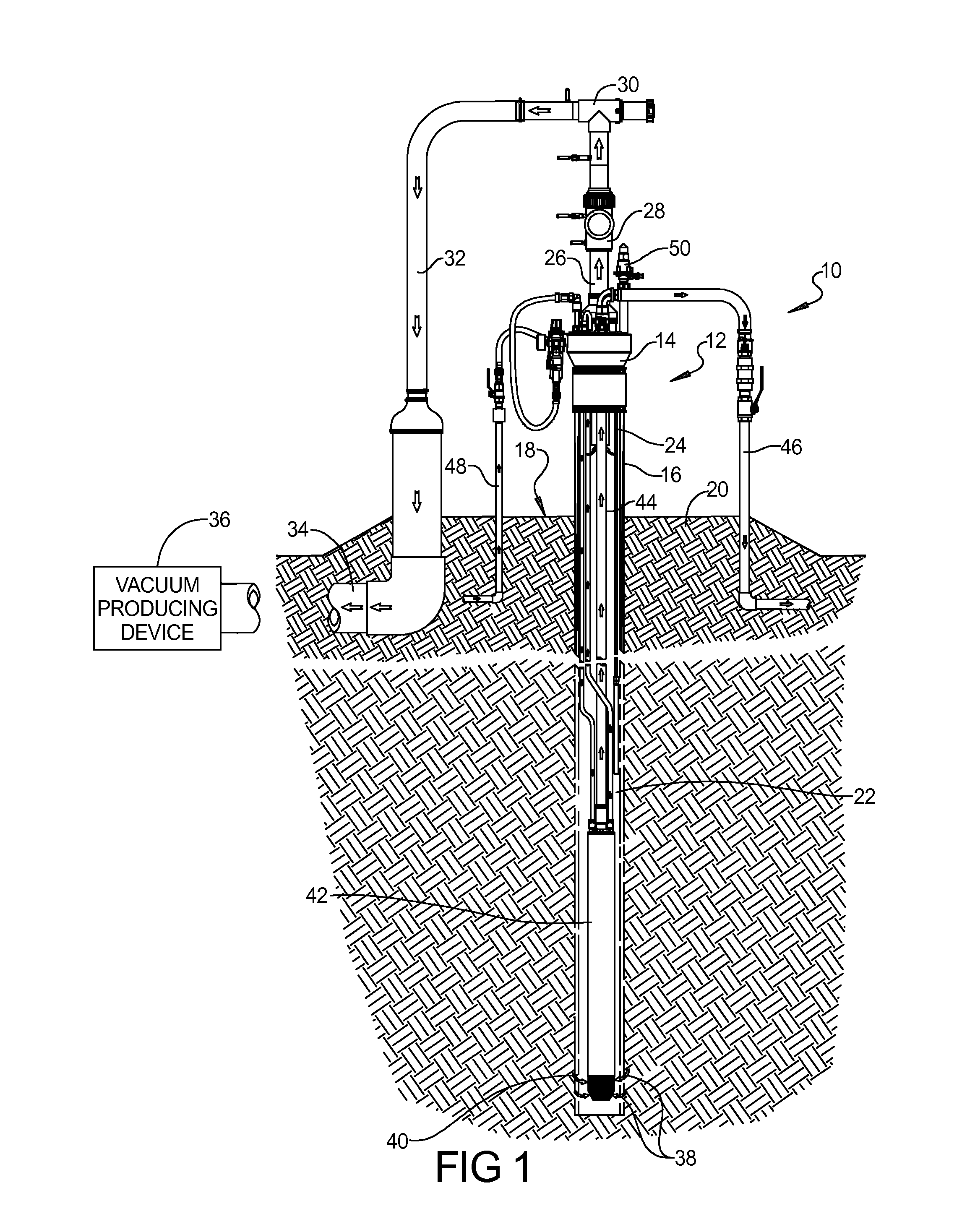
[0025]Referring to FIG. 1, a typical landfill well system 10 includes a well head assembly 12 having a well head 14 mounted to a plastic well pipe 16, which is typically a six inch or eight inch pipe. Well pipe 16 can extend approximately three to four feet above a ground surface 18 of a multiple layer landfill gradient 20, or can be terminated at or below grade or ground surface 18 such that the well head 14 is positioned in a below-ground vault or enclosure. Well pipe 16 includes multiple holes 22 in a zone extending approximately thirty to over one hundred feet below the ground surface 18 that permit influx of landfill gas into the well pipe 16. Landfill gas (i.e., methane gas) is drawn into the collection well 16 into a well discharge pipe 24 that can include an above ground discharge pipe extension 26. The methane gas then passes through multiple components including an orific...


PUM


Abstract

The present disclosure relates to a self-regulating, landfill well control system for automatically controlling a flow of landfill gas (LFG) through a wellhead associated with a landfill well at a landfill. The system has a combination unit operably associated with the wellhead, with a valve actuator, a flow measurement element and a controller. The valve actuator controls a LFG flow control valve, to thus control an LFG flow through the wellhead. The flow measurement element produces differential pressures proportional to a LFG flow rate. The controller controls the valve actuator and, based on data obtained using the flow measurement element, adjusts a setting of the LFG flow control valve to obtain a specific control point setting, and automatically maintains the control point setting thereafter.

Description

CROSS-REFERENCE TO RELATED APPLICATIONS[0001]This application is a continuation of U.S. application Ser. No. 13 / 794,242, filed Mar. 11, 2013, which claims the benefit of U.S. Provisional Application No. 61 / 748,370, filed on Jan. 2, 2013. This application also claims priority to PCT / US2013 / 077508, filed Dec. 23, 2013, which claims priority to U.S. application Ser. No. 13 / 794,242, filed Mar. 11, 2013, and also claims the benefit of U.S. Provisional Application No. 61 / 748,370, filed Jan. 2, 2013. The entire disclosures of the each of the above applications are incorporated herein by reference.FIELD[0002]The present disclosure relates to a system and method for monitoring gas produced by landfills.BACKGROUND[0003]This section provides background information related to the present disclosure which is not necessarily prior art.[0004]Active and inactive domestic solid waste landfills in the United States require the installation of systems to control and capture methane produced by the ana...

Claims


Application Information

Patent Timeline
IPC IPC(8): E21B43/12H04B1/3827E21B47/00H04W4/00B09B3/00E21B34/02H04W4/80
CPCE21B43/12B09B3/0016H04B1/3833E21B47/00H04W4/008E21B34/02E21B44/00H04W4/80B09B1/006E21B34/025B09B3/80
Inventor FISCHER, DAVID A.MIODUSZEWSKI, DAVID
Owner Q E D ENVIRONMENTAL SYST
Why Eureka
Try Eureka