Cooling pipe

A technology of cooling pipes and outer pipes, which is applied in the direction of workpiece cooling devices, workpiece surface treatment equipment, metal rolling, etc., and can solve the problem of optimal cooling water flow rate and pressure, unsatisfactory metallographic structure, uneven cooling of rolled pieces, etc. problem, to avoid the effect of uneven cooling

Pending Publication Date: 2019-01-25
安徽中钢诺泰工程技术有限公司
View PDF0 Cites 1 Cited by
  • Summary
  • Abstract
  • Description
  • Claims
  • Application Information

AI Technical Summary

Problems solved by technology

[0003] In the existing cooling pipes, the water inlet is usually designed as an annular water nozzle surrounding the cooling pipe to ensure uniform water intake, but such a structure alone cannot make the flow rate and pressure of the cooling water in the cooling pipe optim

Method used


Image

  • Cooling pipe
  • Cooling pipe
  • Cooling pipe

Examples


Embodiment Construction

[0025] The invention provides a cooling pipe. On the one hand, its unique structural design reduces the flow rate of cooling water in the pipe, which slows down the rapid cooling speed of the surface of the rolled piece. On the other hand, it also maintains a certain water pressure in the pipe, avoiding the Uneven cooling.

[0026] In order to enable those skilled in the art to better understand the solutions of the present invention, the present invention will be further described in detail below in conjunction with the accompanying drawings and specific embodiments.

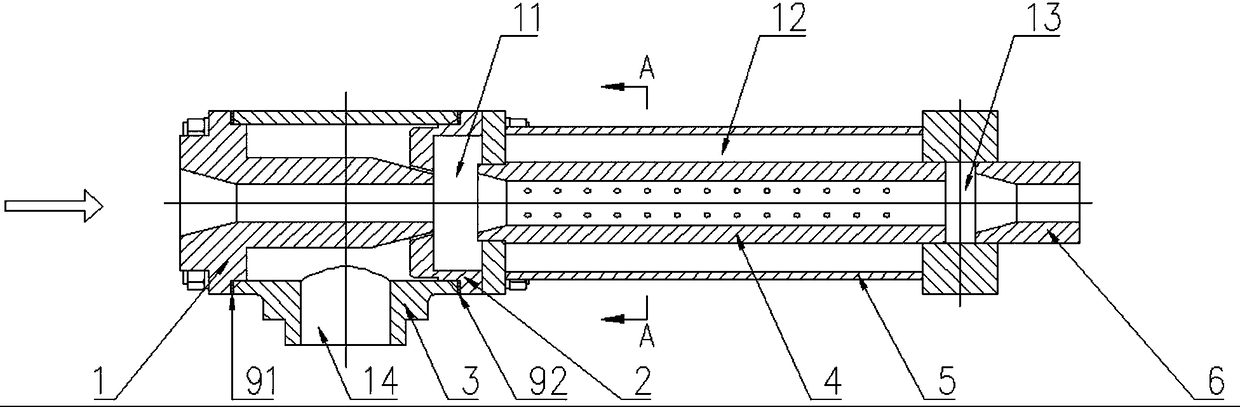
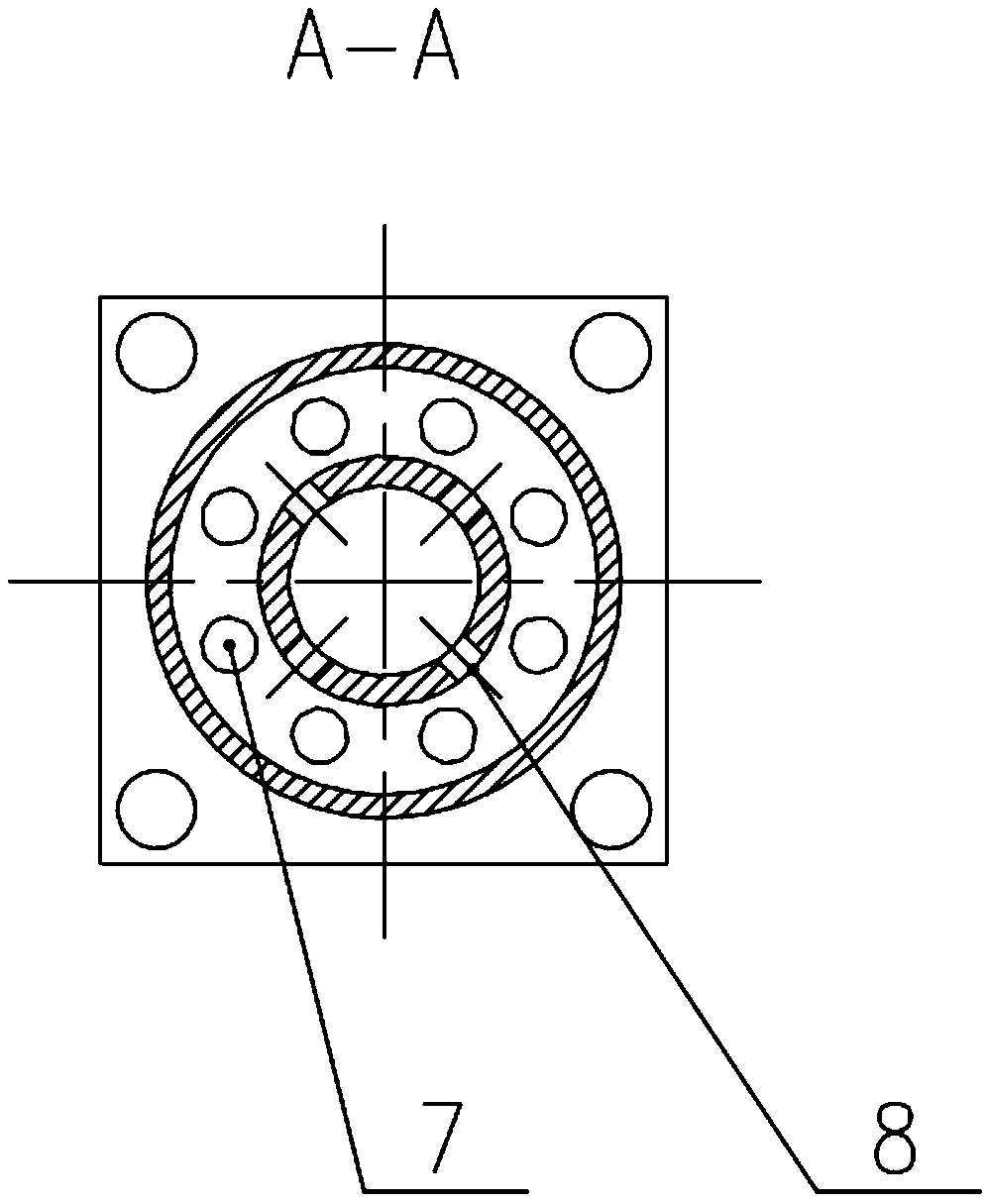
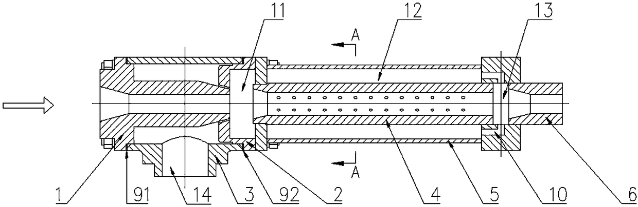
[0027] see figure 1 and figure 2 , a cooling pipe provided in the present invention, comprising a first nozzle 1, a second nozzle 2, an outer pipe 5, an inner conduit 4 and a water inlet 14;

[0028] Wherein, both the first nozzle 1 and the second nozzle 2 are connected at both ends, and are coaxially arranged to form a relative position with an annular water spray port, the inner diameter of the second nozz...


PUM


Abstract

The invention discloses a cooling pipe. The cooling pipe comprises a first spray nozzle, a second spray nozzle, an outer pipe and an inner guide pipe; the two ends of the first spray nozzle are through, the two ends of the second spray nozzle are through, the first spray nozzle and the second spray nozzle are coaxially arrayed to form an opposite portion with an annular water spraying port, the inner diameter of the second spray nozzle is larger than that of the first spray nozzle, and the annular water spraying port extends in the flowing direction of liquid to form a first containing cavity;the outer pipe is coaxially connected to the second spray nozzle, the inner guide sleeve is coaxially sleeved with the outer pipe, and a second containing cavity is formed in a hollow portion betweenthe inner surface of the outer pipe and the outer surface of the inner guide pipe; a first through hole for liquid to flow in is formed between the first containing cavity and the second containing cavity, and a second through hole for liquid to flow in is formed between the second containing cavity and the inner guide pipe. According to the cooling pipe, the flow speed of cooling water in the pipe can be decreased, the cooling speed of the surface of a rolled part is decreased, a certain water pressure is also kept in the pipe, and the rolled part is prevented from being unevenly cooled.

Description

technical field [0001] The invention relates to the technical field of steel rolling equipment, in particular to a cooling pipe. Background technique [0002] After being rolled out of the rolling mill, hot-rolled steel often needs to be cooled by a water cooling device to reach the required temperature and obtain the corresponding metallographic structure. The cooling pipe plays an important role in this process. The inside of the cooling pipe is hollow, and the steel is cooled by the cooling water in the cooling pipe while passing through the cooling pipe. [0003] In the existing cooling pipes, the water inlet is usually designed as an annular water nozzle surrounding the cooling pipe to ensure uniform water intake, but such a structure alone cannot make the flow rate and pressure of the cooling water in the cooling pipe optimal. As a result, the cooling of the rolled piece is not uniform, and the hot-rolled steel will also produce a metallographic structure that does no...

Claims


Application Information

Patent Timeline
IPC IPC(8): B21B45/02
CPCB21B45/0233
Inventor 聂长春
Owner 安徽中钢诺泰工程技术有限公司
Why Eureka
Try Eureka