Low current velocity fluidize cleaning type horizontal column pipe heat transfer equipment system

A technology of heat transfer equipment and low flow rate, which is applied in the field of low flow rate fluidized cleaning type horizontal tube heat transfer equipment system, which can solve the problems of high equipment cost, high flow rate requirements, and difficult cleaning of hard scales.

Inactive Publication Date: 2008-11-12
HUNAN UNIV OF TECH
View PDF1 Cites 1 Cited by
  • Summary
  • Abstract
  • Description
  • Claims
  • Application Information

AI Technical Summary

Problems solved by technology

[0003] The technical problem to be solved by the present invention is the four problems existing in the existing hydrodynamic self-rotating continuous twisted belt cleaning technology: difficult cleaning of hard scale, high equipment cost, and at the same time solve the problem of no heat transfer enhancement in the existing fluidized cleaning in the horizontal tube To solve the two problems of high requirements on function and flow velocity, a low flow velocity fluidized cleaning type horizontal tube heat transfer equipment system is proposed. Clean hard and soft scale, high reliability, low cost, can be widely used in various shell and tube heat transfer equipment with horizontal heat transfer tube or horizontal heat transfer channel structure, such as heat transfer equipment, condenser, evaporator etc.

Method used


Image

  • Low current velocity fluidize cleaning type horizontal column pipe heat transfer equipment system

Examples


Embodiment Construction

[0006] The present invention will be described in further detail below in conjunction with the accompanying drawings.

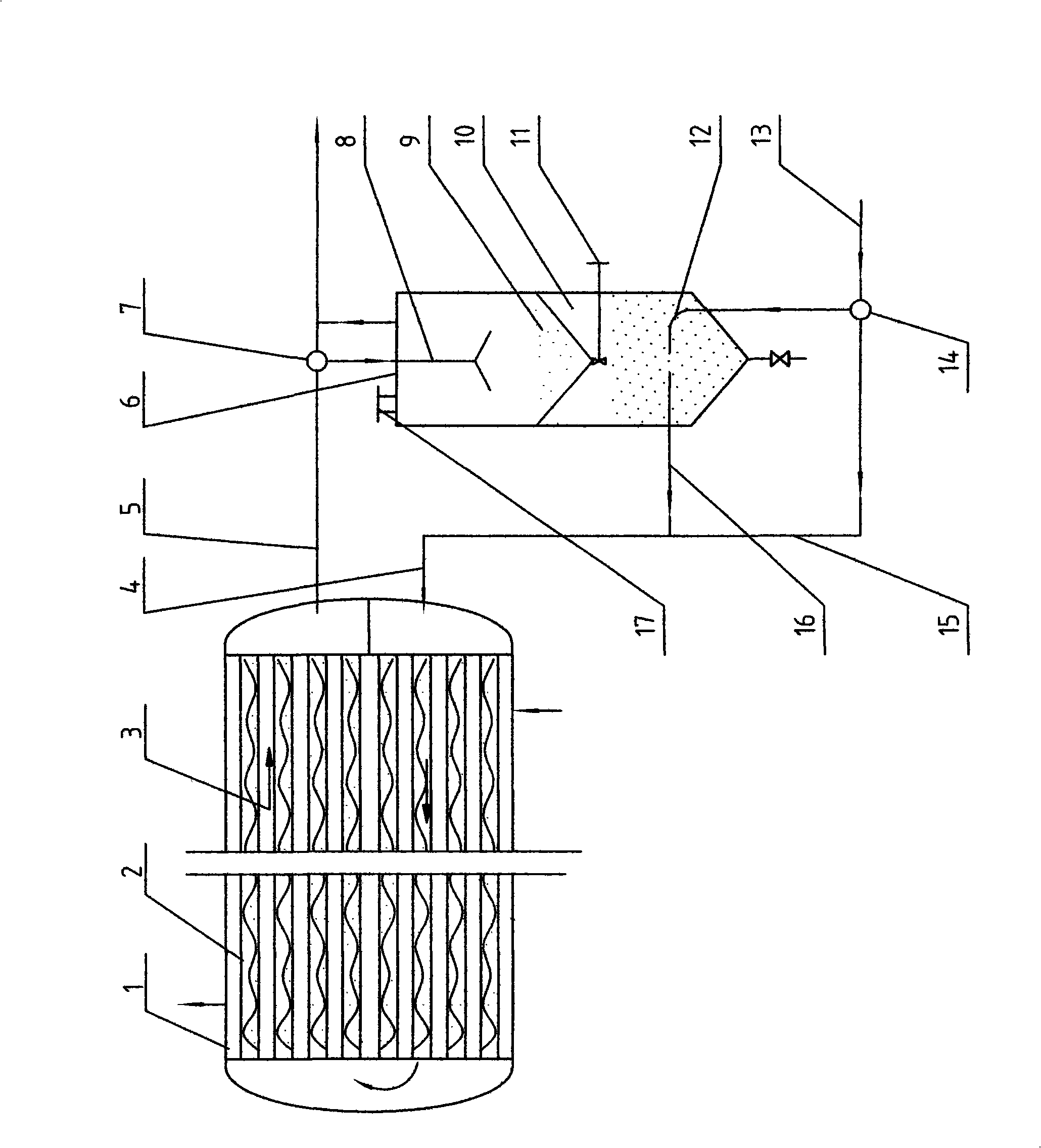
[0007] In the figure 1 heat transfer equipment 2 heat transfer pipe 3 spiral line 4 inlet pipe 5 outlet pipe pipeline 6 circulation tank 7 three-way valve 8 upper part 9 particles 10 lower part 11 communication valve 12 fluidized liquid preparation pipe 13 liquid inlet pipe 14 three-way Valve 15 Clear liquid pipe 16 Fluidized liquid pipe 17 Particle replenishment port

[0008] A low flow rate fluidized cleaning type horizontal tube heat transfer equipment system, a helix 3 is arranged in the heat transfer tube 2 of the heat transfer equipment 1, the length of the helix 3 is roughly equal to the length of the heat transfer tube 2, and the helix 3 The size of the coil is mainly designed according to the requirements of heat transfer enhancement and fluid resistance. The diameter d of the helix 3 can be in the range of 1 to 6 mm, and the pitch T and the inner di...


PUM


Abstract

Disclosed is a fluidization clean-type heat-transfer device system with low flow velocity and horizontal tube array, which is characterized in that: the heat-transfer pipe of the heat-transfer device is internally provided with a helical line which has almost the same length as that of the heat-transfer tube; the inlet and outlet pipe lines of the heat-transfer device are connected with a particle cycling groove; a particle cycling tank is divided into two parts of an upper part and a lower part which are connected with a communication valve; the upper part is the space for the sedimentation and separation of the particles and the lower part is the fluidization space for evenly blending of the fluid and the particles. When in normal running, the convective heat transfer in the tubes is intensified by the helical line, thereby increasing the heat transfer coefficient of the inside of the tubes by about 50 percent; when the fouling of the tubes needs cleaning, a fluidization even cleaning can be realized at a relatively low flow velocity of 0.45 m / s in the heat-transfer tubes by a convenient operation of switching two three-way valves. The novel heat-transfer device has high heat-transfer efficiency, simple structure, high reliability, simple operation and can be widely applied to various horizontal-type heat-transfer devices with a tube array structure.

Description

technical field [0001] The invention relates to a low flow rate fluidized cleaning type horizontal tube heat transfer equipment system, and relates to the enhancement of heat transfer in the tube of the horizontal tube heat transfer equipment and online cleaning of dirt. It is suitable for various shell and tube heat transfer equipment with horizontal heat transfer tubes, such as heat transfer equipment, condensers, evaporators, etc. Background technique [0002] There are many existing technologies for heat transfer enhancement and on-line cleaning of dirt in horizontal heat transfer tubes. The self-rotating plastic-coated helix technology (ZL2004200351029, Hydrodynamic plastic-coated helix for online automatic cleaning of dirt in heat transfer tubes, 2005.2.20.), self-rotating plastic smooth twisted belt technology (Yu Tianlan, Peng Deqi , Yu Xiumin, etc. Research on automatic on-line continuous descaling and anti-scaling technology for steam turbine condenser self-rotati...

Claims


Application Information

Patent Timeline
Patent Type & Authority Applications(China)
IPC IPC(8): F28F13/00F28G1/12F28D7/10F28D7/16
Inventor 俞天兰彭德其李群松蒋少青俞秀民俞天翔吴金香支校衡刘桂英吴琦华
Owner HUNAN UNIV OF TECH
Why Eureka
Try Eureka