
Process for Producing Polyethylene Porous Film and Polyethylene Porous Film

a technology of polyethylene porous film and polyethylene porous film, which is applied in the direction of cell components, cell components, membranes, etc., can solve the problems of short circuit of batteries, polyethylene porous film in which the pores are formed, and environmental load with volatilization of organic solvent becomes problematic, etc., to achieve high gas permeation coefficient, large pore volume, and specific surface area

Active Publication Date: 2015-09-24
GUNMA UNIVERSITY
View PDF1 Cites 1 Cited by
  • Summary
  • Abstract
  • Description
  • Claims
  • Application Information

AI Technical Summary

Benefits of technology

The present invention provides a polyethylene porous film with small micropore sizes, large pore volume, specific surface area, and high gas permeation coefficient. The process for producing the film does not include shrinkage treatment, making it simpler to produce than other methods. The film has high tensile breaking strength and tear strength. Additionally, the invention provides a method for producing a polyethylene porous film with improved air permeability by adjusting the film's pore size and porosity. The film is suitable for various applications such as gas separation, air purification, and breathable materials.

Problems solved by technology

Thus, although a method of increasing the pore diameter of the separator has been employed, when the pore diameter is 1 μm or more, lithium ions in an organic electrolyte crystallize and deposite in a dendrite (arboroid) form as metallic lithium, whereby energization occurs, so that there occurs a problem that short circuiting of a battery occurs.
Accordingly, the production of the polyethylene porous film in which the pores are formed by removal of a large amount of the organic solvent is complex, and environmental load with volatilization of the organic solvent becomes problematic.
However, a process for dissolving and removing the inorganic fine powder is also complex, and there is a restriction that an obtained pore diameter in principle cannot be made smaller than the size of the inorganic fine powder used in the formation of pores.

Method used


Image

  • Process for Producing Polyethylene Porous Film and Polyethylene Porous Film
  • Process for Producing Polyethylene Porous Film and Polyethylene Porous Film
  • Process for Producing Polyethylene Porous Film and Polyethylene Porous Film

Examples


example 1

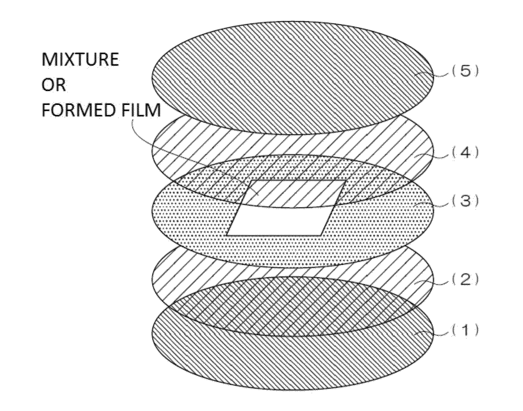
(a) Mixture Preparation Process

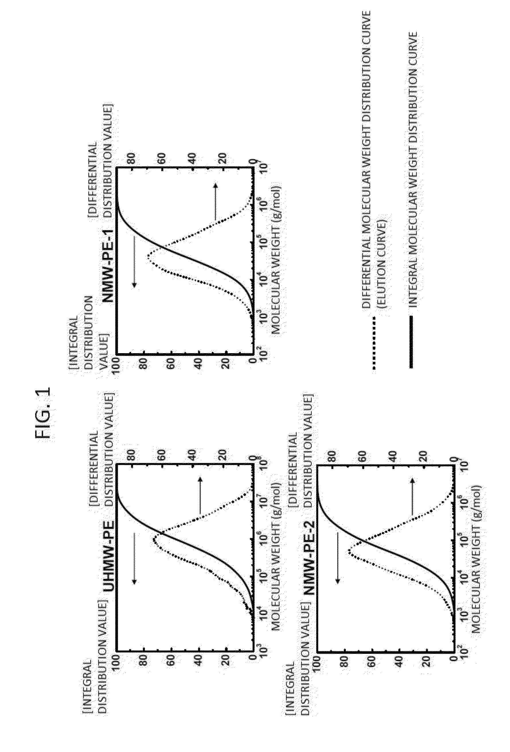
[0196]Powdered UHMW-PE (Hizex Million 340M produced by Mitsui Chemicals, Inc., My=3.5×10⁶, average particle diameter: 150 μm), powdered NMW-PE-1 (J-REX KX285N produced by Japan Polyolefins Corporation, Mw=1.1×10⁵, average particle diameter: 300 μm), and powdered NMW-PE-2 (Mw=1.4×10⁵, average particle diameter: 250 μm) are provided.

[0197]The following table 1 shows details of those polyethylene raw materials. The polyethylene raw materials are those synthesized using Ziegler-based catalysts.

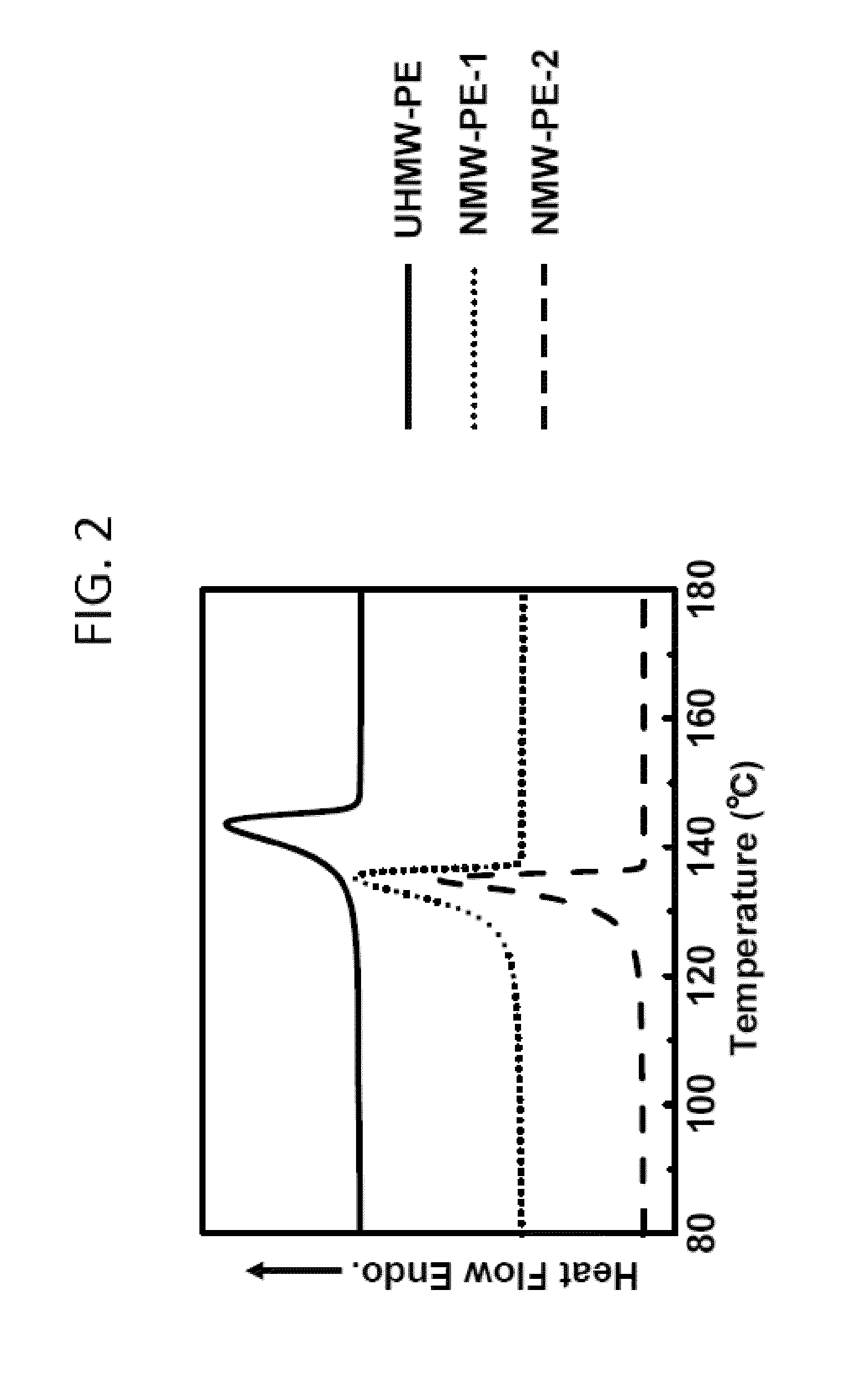
TABLE 1ViscosityWeightNumberMolecularaverageaverageaverageweightMeltingmolecularmolecularmoleculardistri-pointweight Mvweight Mwweight MnbutionTm(g / mol)(g / mol)(g / mol)Mw / Mn(° C.)UHMW-PE3.5 × 1061.8 × 1062.3 × 1057.8140.1NMW-PE-1—1.1 × 1051.7 × 1046.0136.3NMW-PE-2—1.4 × 1052.1 × 1046.5135.0

[0198]The melting point (Tm) of each of those polyethylene raw materials is the endothermic peak temperature (° C.) estimated from a DSC melting profile shown in FIG. 2.

[0199]With re...

example 2

[0238]In Example 2, a polyethylene porous film was obtained similarly to Example 1, except that the mixing ratio of UHMW-PE and NMW-PE-1 was changed to 50:50.

[0239]When the oxygen permeation coefficient and the mechanical strength of a heat-treated film before the pore formation treatment were measured similarly to Example 1, the oxygen permeation coefficient was 2.33×10⁻¹⁵ mol·m / (m2·s·Pa), and the tensile breaking strength was 20.5 MPa.

[0240]The obtained polyethylene porous film of Example 2 was evaluated similarly to Example 1. As a result, the average pore diameter was 90.9 nm, the specific surface area was 100.3 m2 / g, and the porosity was 34.2%.

[0241]Meanwhile, the oxygen permeation coefficient was 9.04×10⁻¹¹ mol·m / (m2·s·Pa), and it was found that the polyethylene porous film of Example 2 exhibits an excellent pore communication property.

[0242]Further, the tensile breaking strength of the polyethylene porous film of Example 2 was 29.7 MPa, and it was found that the polyethylene ...

example 3

[0244]In Example 3, a polyethylene porous film was obtained similarly to Example 1, except that the mixing ratio of UHMW-PE and NMW-PE-1 as raw materials was changed to 60:40.

[0245]The obtained polyethylene porous film of Example 3 was evaluated similarly to Example 1. As a result, in the polyethylene porous film of Example 3, the average pore diameter was 89.0 nm, the specific surface area was 239.9 m2 / g, and the porosity was 53.8%.

[0246]The oxygen permeation coefficient was 8.27×10⁻¹² mol·m / (m2·s·Pa), and it was found that the polyethylene porous film of Example 3 exhibits an excellent pore communication property.

[0247]Further, the tensile breaking strength of the polyethylene porous film of Example 3 was 29.8 MPa, and it was found that the polyethylene porous film of Example 3 has excellent mechanical properties.


PUM

PropertyMeasurementUnit
temperatureaaaaaaaaaa
porosityaaaaaaaaaa
specific surface areaaaaaaaaaaa

Abstract

Disclosed is a polyethylene porous film having an average pore diameter of 200 nm or less, a specific surface area of 50 m2 / g or more, and a porosity of 15% or more, each of which is measured by a mercury intrusion method at room temperature, the polyethylene porous film being obtained by forming pores only by drawing a film containing an ultrahigh molecular weight polyethylene having a viscosity average molecular weight of from 1 million to 15 million and a polyethylene having a weight average molecular weight of from 10,000 to 800,000 at a mass ratio of from 50:50 to 99:1. The polyethylene porous film is produced by molding a film using a mixture of the ultrahigh weight polyethylene and the polyethylene having a weight average molecular weight of from 10,000 to 800,000, biaxially drawing the film, then heat-treating and redrawing the film to form pores in the film.

Description

TECHNICAL FIELD[0001]The present invention relates to a process for producing a polyethylene porous film, which has so small micropore diameter as nm order (200 nm or less), high tensile breaking strength and tear strength while having large pore volume and specific surface area, and has a high gas permeation coefficient, and a polyethylene porous film obtained by the producing process.BACKGROUND ART[0002]A polyethylene porous film is used as a separator of a lithium ion battery. In order to make the voltage of the lithium ion battery higher, it is effective to increase the pore volume of a separator so that lithium ions can further smoothly move between electrodes. Thus, although a method of increasing the pore diameter of the separator has been employed, when the pore diameter is 1 μm or more, lithium ions in an organic electrolyte crystallize and deposite in a dendrite (arboroid) form as metallic lithium, whereby energization occurs, so that there occurs a problem that short circ...

Claims


Application Information

Patent Timeline
Patent Type & Authority Applications(United States)
IPC IPC(8): H01M2/16B32B27/08B32B27/32B32B3/26H01M50/417H01M50/489H01M50/494
CPCH01M2/1653B32B3/26B32B2457/10B32B27/32B32B2307/718B32B27/08H01M10/0525B01D67/0027B01D2323/12B01D2325/04Y02E60/10H01M50/417H01M50/489H01M50/494B01D71/261B29C55/02B29K2023/0683
Inventor UEHARA, HIROKIYAMANOBE, TAKESHITANAKA, HIDEKAZU
Owner GUNMA UNIVERSITY
Learn More