High-Efficiency, Wide Dynamic Range Dimming for Solid-State Lighting

a technology of solid-state lighting and dynamic range, which is applied in the direction of electric lighting sources, electroluminescent light sources, and semiconductor lamp usage, can solve the problems of voltage drop across the dimming of the light emitted by one or more light-emitting devices, so as to achieve wide dimming range and reduce voltage

Active Publication Date: 2015-08-27
MCCUNE JR EARL W
View PDF13 Cites 18 Cited by
  • Summary
  • Abstract
  • Description
  • Claims
  • Application Information

AI Technical Summary

Benefits of technology

[0007]Systems and methods for controlling dimming in solid-state lighting (SSL) systems are disclosed. An exemplary SSL lighting system for controlling dimming includes a variable dim setting resistor, one or more light-emitting devices, an adjustable regulator, and a sensor for measuring or sensing a current flowing through the variable dim setting resistor. The variable dim setting resistor is coupled in series with the one or more light-emitting devices and is configured to receive a dim control signal which sets and controls the resistance of the variable dim setting resistor. The adjustable regulator is configured to generate an adjustable and regulated power supply for powering the dim setting resistor and the one or more light-emitting devices. The sensor is disposed in a feedback loop between the variable dim setting resistor and an adjust input of the adjustable regulator and in one embodiment of the invention comprises an operational amplifier (op-amp) circuit which operates to maintain a constant voltage across the dim setting resistor, independent of the value of the dim control signal and resistance of the variable dim setting resistor. Upon the sensor measuring or sensing that the current flowing through the dim setting resistor has increased (the increase indicating that the variable dim setting resistor has been adjusted lower), the op-amp circuit generates an adjust signal for the adjustable regulator, causing the adjustable regulator to reduce the voltage it generates and supplies. The lower supply voltage causes the voltage drop across the one or more light-emitting devices to also decrease, resulting in a dimming of the light emitted by the one or more light-emitting devices. Test measurements have shown that the SSL systems of the present invention are capable of dimming over an extremely wide dimming range. For example, measurements have shown that not only are the SSL systems capable of a dimming ratio of greater than 1000:1, they have also shown that a dimming ratio exceeding 20,000:1 can be achieved.

Problems solved by technology

The lower supply voltage causes the voltage drop across the one or more light-emitting devices to also decrease, resulting in a dimming of the light emitted by the one or more light-emitting devices.

Method used


Image

  • High-Efficiency, Wide Dynamic Range Dimming for Solid-State Lighting
  • High-Efficiency, Wide Dynamic Range Dimming for Solid-State Lighting
  • High-Efficiency, Wide Dynamic Range Dimming for Solid-State Lighting

Examples


Embodiment Construction

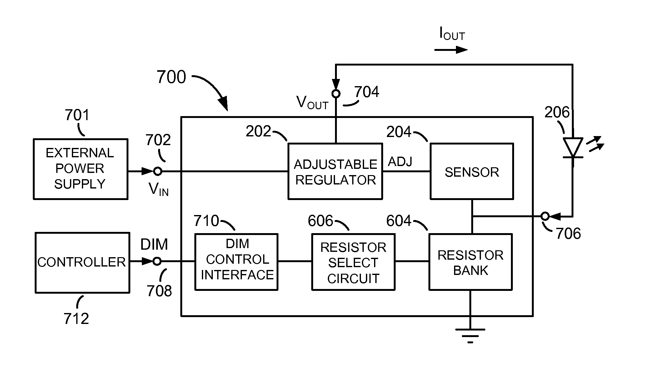
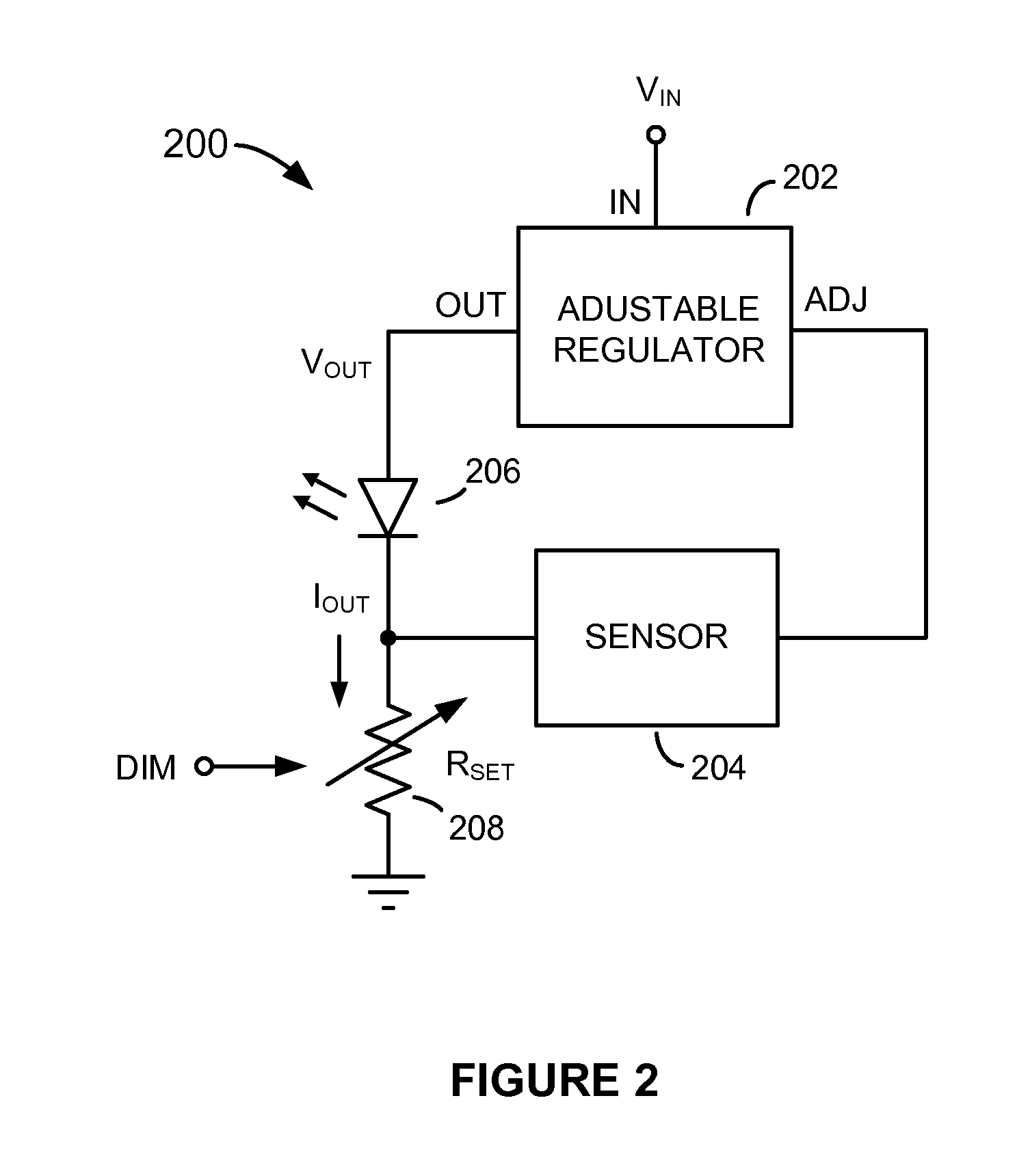
[0016]Referring to FIG. 2, there is shown a solid-state lighting (SSL) system 200 having extremely wide-range dimming capability, according to an embodiment of the present invention. The SSL system 200 comprises an adjustable regulator 202, a current sensor 204, a light-emitting device 206, and a variable dim setting resistor RSET 208. In the description that follows the SSL system 200 is described as controlling dimming of a single light-emitting diode (LED) 206. However, those of ordinary skill in the art will appreciate and understand that the SSL system 200 can be used to control dimming of a plurality of LEDs (e.g., a string of light-emitting devices). Further, the invention is not limited to controlling dimming of LEDs. It can be used or adapted to control dimming of other types of light-emitting devices, such as laser diodes, for example.

[0017]As shown in FIG. 2, the adjustable regulator 202 has an input power terminal (IN) that is configured to receive an input voltage Vin f...


PUM


Abstract

A solid-state lighting system includes a light-emitting device connected in series with a variable dim setting resistor, an adjustable regulator, and a current sensor disposed in a feedback loop between an adjust input of the adjustable regulator and the variable dim setting resistor. The voltage dropped across the variable dim setting resistor is forced to remain constant irrespective of the resistance setting of the dim setting resistor. The current sensor measures or senses the current flowing through the variable dim setting resistor and causes the adjustable regulator to adjust its output voltage and the forward voltage drop across the light-emitting device so that the current flowing through the light-emitting device matches the current set by the variable dim setting resistor. Controlling the current in this manner allows dimming to be performed over an extremely wide dimming range, to very low light levels, and without producing light flicker at any dim level.

Description

CROSS-REFERENCE TO RELATED APPLICATIONS[0001]This patent application claims the benefit of U.S. Provisional Patent Application No. 61 / 944,149, filed on Feb. 25, 2014, the disclosure of which is incorporated herein by reference.FIELD OF THE INVENTION[0002]The present invention relates in general to solid-state lighting (SSL) systems and in particular to methods and apparatus for performing dimming in SSL systems over an extremely wide dimming range and to very low dimming levels.BACKGROUND OF THE INVENTION[0003]Solid-state lighting (SSL) is rapidly becoming commonplace in many areas of modern society. SSL employs light-emitting diodes (LEDs), which are inexpensive, durable, small in size, energy-efficient, and long-lasting. This desirable combination of attributes is not present in more conventional lighting sources, such as incandescent and fluorescent lighting sources.[0004]In some circumstances it is necessary or desirable to control dimming of the light produced by a lighting sys...

Claims


Application Information

Patent Timeline
Patent Type & Authority Applications(United States)
IPC IPC(8): H05B33/08H05B44/00
CPCH05B33/0851H05B33/0812H05B33/0815H05B33/089H05B45/395H05B45/10Y02B20/30H05B45/14
Inventor MCCUNE, JR., EARL W.
Owner MCCUNE JR EARL W
Why Eureka
Try Eureka