
Optimized method of coating the microwave ablation probe for surgical application

a microwave ablation and surgical technology, applied in the field of surgical microwave ablation probes, can solve the problems of local tissue burning instead of regional or uniform heating and uncontrolled current concentrations

Inactive Publication Date: 2015-08-06
CEDARS SINAI MEDICAL CENT
View PDF0 Cites 1 Cited by
  • Summary
  • Abstract
  • Description
  • Claims
  • Application Information

AI Technical Summary

Benefits of technology

This patent discusses a new neurological microwave ablation probe that uses a special coating called parylene C to improve its heating of brain tissue. This coating is applied to the probe tip and the anode (positive electrode) to provide better electrical isolation and control of the heating process. The coating is deposited at room temperature and is effective as a moisture diffusion barrier. The patent also explains the advantages of using parylene C compared to other coatings, such as its higher deposition rate and ability to provide better control over heating.

Problems solved by technology

The heating of the tissue is intended to occur from noncontact dielectric heating as opposed to ohmic heating by direct conduction of microwave current in the tissue, which could result in uncontrolled current concentrations and local tissue burning instead of regional or uniform heating.
In conventional construction it is possible that in some cases fluid leakage under the discrete insulation layers provided to cover the ablation tip could occur from time to time or that microscopic cracks or other defects in the insulation layer could allow electrical conduction therethrough, particularly through conductive intermediate fluids occurring in the surgical theater.
The problem to solve is to have a biocompatible seal over the probe materials that is adequately robust to remain electrically and mechanically uncompromised throughout its life up to and including the surgical procedure.

Method used


Image

  • Optimized method of coating the microwave ablation probe for surgical application
  • Optimized method of coating the microwave ablation probe for surgical application
  • Optimized method of coating the microwave ablation probe for surgical application

Examples


Embodiment Construction

[0034]One ablation system in which the probe could be used is substantially similar to that disclosed in U.S. Pat. No. 5,301,687 and U.S. Pat. No. 6,706,040, incorporated herein by reference.

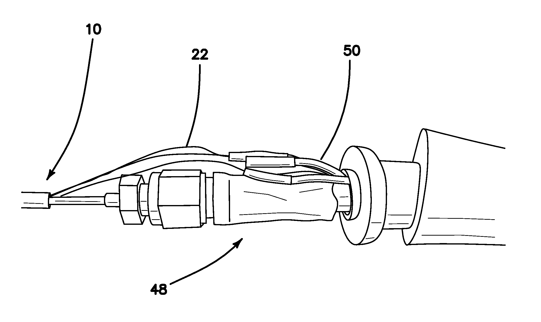
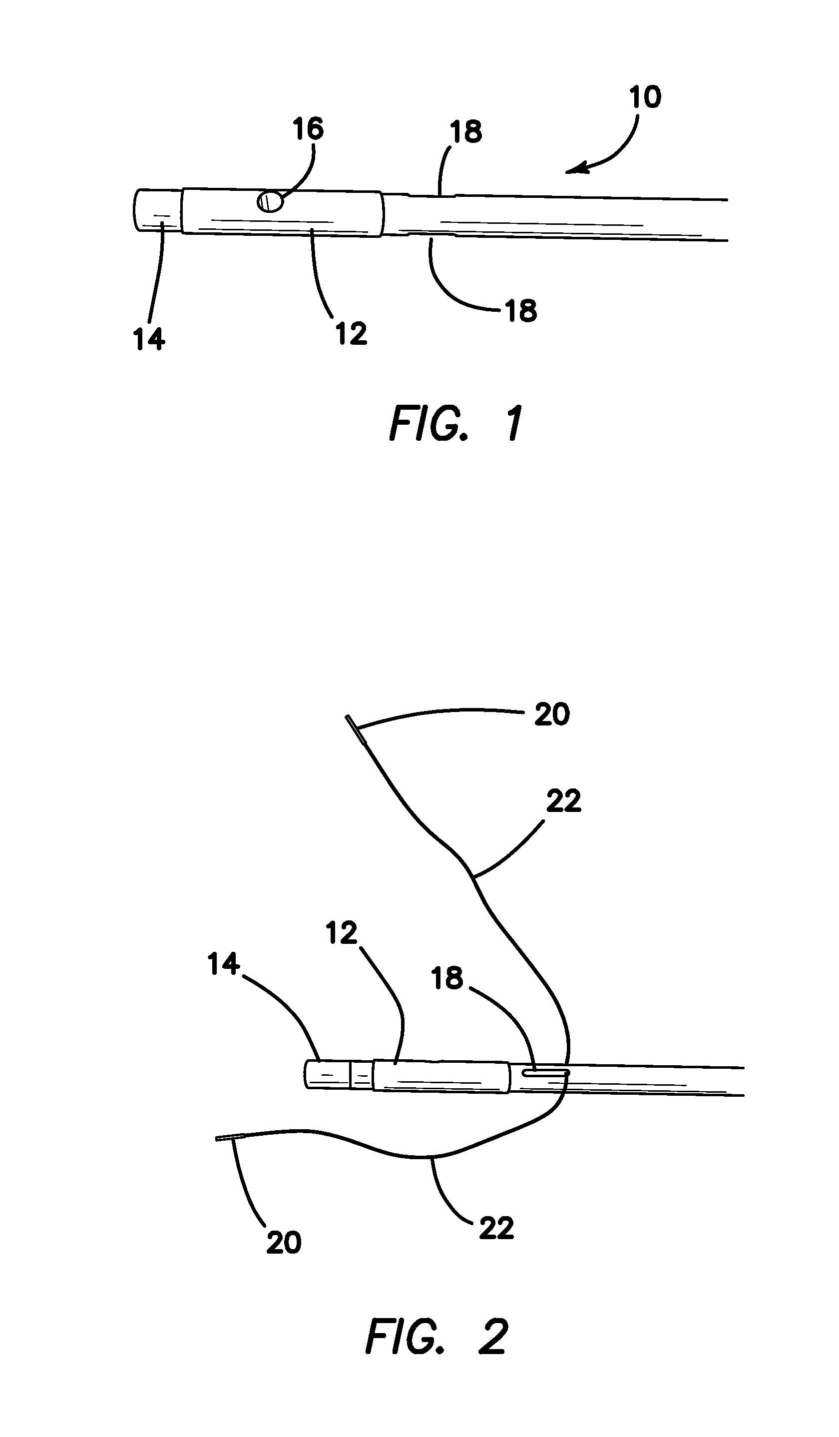
[0035]FIG. 1 is a diagram showing the first step in the manufacture of the microwave ablation probe 10 of the invention, wherein the distal end of ablation probe 10. The probe 10 includes a hollow fiberglass tube 14 having an outer diameter of 2.3 mm and an inner diameter of 1.6 mm, serving as a core of the probe 10. In the illustrated embodiment probe 10 is 7.5 inch (19.05 mm) long. A metallic anode sleeve 12 made of Brass 260 Alloy is slid over the distal end of tube 14 and spaced 0.075±0.010 inch (1.905±0.25 mm) from the end. A 0.03 inch (0.762 mm) through-bore hole 16 is drilled or defined completely through anode 12 and tube 14. A pair of diametrically opposing slots 18 are defined through the walls of tube 14 extending from the proximal end of anode 12 for approximately 0.14 inch (3.56 mm)...


PUM

PropertyMeasurementUnit
Temperatureaaaaaaaaaa
Thicknessaaaaaaaaaa

Abstract

An ablation probe which includes a probe body with a distal and proximal end, an ablation tip at the distal end of the probe body, an anode provided proximate to the ablation tip, a coaxial cable disposed within the probe body and coupled to the ablation tip and anode so that electromagnetic energy of a predetermined frequency is communicated thereto for dielectric heating of tissue, and a Parylene C coating on at least the ablation tip and anode to electrically isolate the ablation tip and anode from tissue without interference with microwave energy transmission through the probe to the tissue. The Parylene C is a vapor deposited coating on at least the ablation tip and anode to electrically isolate the ablation tip and anode from tissue.

Description

RELATED APPLICATIONS[0001]The present application is related and claims priority to U.S. Provisional Application Ser. No. 61 / 936,786, filed on Feb. 6, 2014, pursuant to 35 USC 119, which application is incorporated herein in its entirety.FIELD OF THE INVENTION[0002]The disclosure relates to the field of surgical microwave ablation probes to treat cancers or any disorders of brain, breast, liver, pancreas / GI, prostate and head and neck.BACKGROUND[0003]Ablative procedures increase the tumor temperature (50° C. to 80° C.), which modifies tumor cell morphology and function. The heat causes coagulation of cellular proteins and leads to tumor cell death when temperatures exceed 50° C. (Nikfarjam et al. 2005). Microwave ablation is a newer technology that utilizes an electromagnetic field to vibrate the water molecules in the treated tissue. This generates the heat that causes disruption of cellular proteins and apoptosis (cell death). This method has certain advantages over RF ablation as...

Claims


Application Information

Patent Timeline
IPC IPC(8): A61B18/18
CPCA61B18/1815A61B2018/00446A61B2018/00577A61B2017/00526A61B2018/1884A61B2018/1892A61B2017/00929A61B2018/183A61B2018/00107A61B2018/00136A61B2018/00797A61B2018/00815A61B2018/1861
Inventor KATEB, BABAKHAMMERSLAG, EDWARD DEANGALAN, HOSMEL
Owner CEDARS SINAI MEDICAL CENT
Learn More