High efficiency organic light emitting devices

Active Publication Date: 2015-07-23
RGT UNIV OF CALIFORNIA
View PDF5 Cites 6 Cited by
  • Summary
  • Abstract
  • Description
  • Claims
  • Application Information

AI Technical Summary

Benefits of technology

The patent is about a new method for making flexible light-emitting devices using a composite electrode with conductive nanowires and a polymer layer with light-emitting properties. This method allows for the fabrication of large-area devices using solution processing. The devices made using this method show improved electroluminescence efficiency and can also include light-scattering particles to increase efficiency. The technical effects of this patent are a more efficient and flexible method for making light-emitting devices with improved performance and lower costs.

Problems solved by technology

However, some of the originally perceived major advantages of OLEDs have not been fully realized in commercial products.
However, the flexibility of these devices is limited by the glass substrate or by the ITO coating.
In addition, flexible OLEDs based on ITO / plastic substrate have exhibited generally low performance and rather limited flexibility.
High performance OLEDs that are generally fabricated on ITO / glass and are not flexible.
Furthermore, the emission efficiency of OLEDs is limited due to waveguiding in the ITO layer as well as the substrate layer.
Conventional OLEDs also employ a cathode that is deposited by physical vapor deposition in a high vacuum which is costly.
Vapor deposition methods such as plasma vapor deposition (PVD) or chemical deposition (CVD) schemes require complicated equipment and a substantial capital investment, greatly increasing the cost of the device fabrication process.
In addition, the materials available for use in conventional vapor deposition processes are limited to mainly metal oxides or mixed metal oxides, such as indium-tin mixed oxide (ITO), antimony-tin mixed oxide (ATO), fluorine-doped tin oxide (FTO), and aluminum-doped zinc oxide (Al—ZO).
Unfortunately electrodes produced from these metal oxide materials are found to be brittle and adhesion to the substrate is poor.
Such electrodes do not survive repeated deformations.
Accordingly, there are several key challenges that have yet to be overcome for all-solution processing: 1) the limited selection of a transparent anode.
ITO coating requires a high vacuum and high temperatures.
While several alternative technologies have been studied, none of them can match the performance of ITO / glass.
3) For efficient injections of charge carriers, the emissive organic layer has to be thinner than 100 nm, and multiple layers are preferred, which make all-solution processing rather difficult.

Method used


Image

  • High efficiency organic light emitting devices
  • High efficiency organic light emitting devices
  • High efficiency organic light emitting devices

Examples


example 1

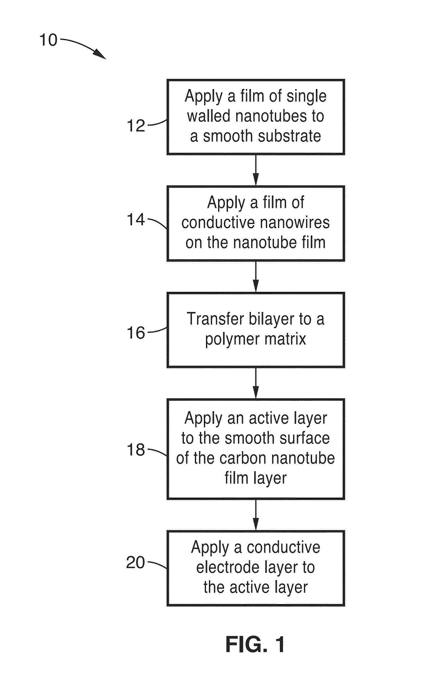
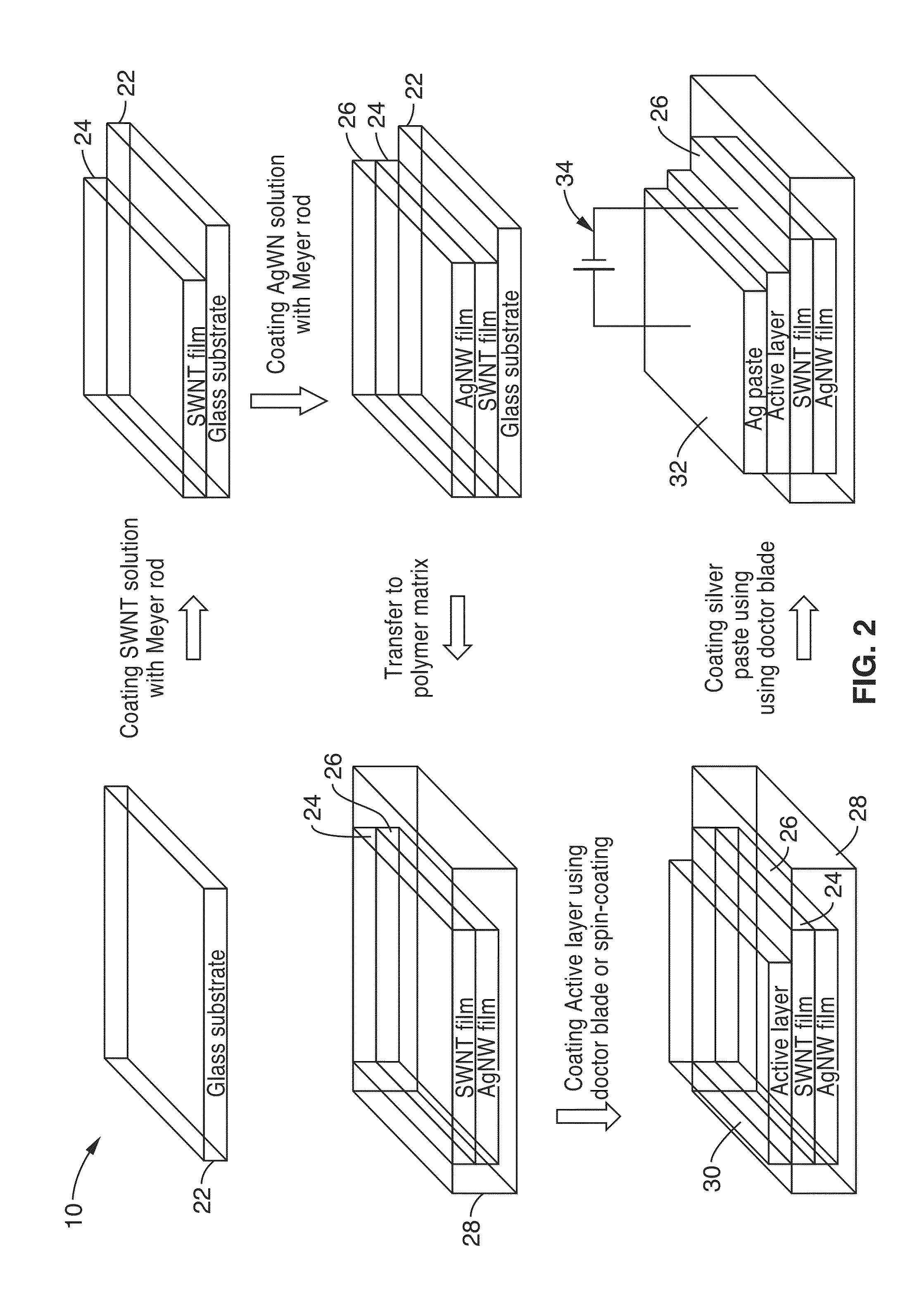
[0046]In order to demonstrate the functionality of the technology, LEO devices with one single walled carbon nanotube / Ag nanowires bilayer-polymer composite electrode were fabricated. Referring now to FIG. 2, a glass substrate 22 was provided and coated with a layer of single walled carbon nanotubes (SWCNT) 24 from a dispersion of nanotubes in isopropanol (IPA) and deionized water. In this procedure, 10 mg of functional SWCNTs were dispersed in 10 ml of a distilled water (DI-water) and isopropanol alcohol (IPA) mixture solution (volume ratio: DI-water / IPA=1 / 4) with the aid of sonication. The dispersion was subjected to centrifugation (at 8,000 rpm for 20 min) to remove undispersed SWCNT agglomerates and other large impurities. The resulting solution was then coated employing the Meyer rod on the glass release substrates to produce the SWCNT film 24.

[0047]The resulting carbon nanotube layer 24 was followed by a layer 26 of silver nanowires (AgNW)s from a dispersion of nanowires in IP...

example 2

[0057]The transmittance properties of the SWCNT films, bilayer films and the polymer composites were measured. A comparison of transmittance and sheet resistance performance for composite electrodes and ITO-glass electrode is tabulated in Table 1.

[0058]The transmittance spectra for the 10,000 ohm / sq SWCNT coating and various SWCNT / AgNW bilayer coatings on glass substrate were collected and evaluated. Although the SWCNT network is densely packed in stark contrast with that of the AgNW coating, the transmittance of the 10,000 Ω / sq SWCNT coating at 550 nm is around 89% (inclusive of glass substrate) and the 30 Ω / sq sheet resistance had an 85% transmittance at 550 nm. When the sheet resistance of SWCNT coatings is lowered to 1.5 kΩ / sq in thicker coatings, the transmittance would diminish to only 76% at 550 nm. To lower to less than 100 Ohm / sq, the transmittance would be less than 60% at 550 nm, which is undesirable as a transparent electrode for PLECs.

[0059]The 10,000 Ω / sq SWCNT coating...

example 3

[0062]The device structure and performance of LEO devices with ITO / glass, SWCNT-polymer composite, AgNW-polymer composite or SWCNT / AgNW bilayer-polymer composite electrode as anodes, and evaporated Al or Ag paste as cathodes were evaluated and tabulated in Table 2.

[0063]The commercial printing Ag paste has been used as the cathode in polymer LEDs. To investigate the performance of LEO devices using Ag paste as cathode, we first compared the two devices A and B of Table 2 using the same active layer (OC1C10:IC:LiTf) and anode (ITO / glass), but with evaporated Al (device A) and printing Ag paste (device B) as cathode respectively.

[0064]The current density-luminance-driving voltage characteristic curves (J-L-V) and current efficiency-luminance characteristic curves (η-L) of device A and device B, measured at a scanning voltage of 0.1 V / s, are presented with the corresponding maximum current efficiency, brightness, voltage and current density listed in Table 2.

[0065]The control device A ...


PUM

PropertyMeasurementUnit
Heightaaaaaaaaaa
Sheet resistanceaaaaaaaaaa
Electrical conductoraaaaaaaaaa

Abstract

A method for producing high efficiency organic light emitting devices, that have an organic semiconductor active layer sandwiched between electrodes where at least one of the electrodes is a film of conductive nanowires, carbon nanoparticles, light scattering nanoparticles and a polymer support. The light scattering nanoparticles can be incorporated in the conductive nanowires, carbon nanoparticle or polymer support elements of the electrode. The second electrode can be identical to the first to provide a symmetrical device or can be a conductive paste or metal layer. The entire process, including the formation of both of the electrodes, the emissive polymer layer, and the substrate, may be carried out by solution processing.

Description

CROSS-REFERENCE TO RELATED APPLICATIONS[0001]This application is a 35 U.S.C. §111(a) continuation of PCT international application number PCT / US2013 / 051349 filed on Jul. 19, 2013, incorporated herein by reference in its entirety, which claims priority to, and the benefit of, U.S. provisional patent application Ser. No. 61 / 674,197 filed on Jul. 20, 2012, incorporated herein by reference in its entirety. Priority is claimed to each of the foregoing applications.[0002]The above-referenced PCT international application was published as PCT International Publication No. WO 2014 / 015284 on Jan. 23, 2014, which publication is incorporated herein by reference in its entirety.STATEMENT REGARDING FEDERALLY SPONSORED RESEARCH OR DEVELOPMENT[0003]This invention was made with Government support under 1028412, awarded by the National Science Foundation; and, Government support under FA9550-12-1-0074, awarded by the U.S. Air Force, Air Force Office of Scientific Research. The Government has certain...

Claims


Application Information

Patent Timeline
IPC IPC(8): H01L51/52H01L51/00H01L51/56H01L51/50
CPCH01L51/5268H01L51/5215H01L51/56H01L51/0037H01L51/5012H01L51/5056B82Y10/00H10K85/221H10K50/135H10K50/11H10K2101/10H10K50/81H10K50/816H10K50/854H10K2102/331H10K2102/311H10K50/15H10K71/00H10K85/1135
Inventor PEI, QIBING
Owner RGT UNIV OF CALIFORNIA
Why Eureka
Try Eureka