
Spectrally encoded microbeads and methods and devices for making and using same

a technology of microbeads and encoding methods, applied in the field of spectrally encoded microbeads and methods and devices for making and using same, can solve the problems of limited practical application of bead encoding to date, new approaches are needed, and few practicable cost-effective assays for multiplexing exist. to achieve the effect of facilitating preparation and us

Active Publication Date: 2015-07-09
RGT UNIV OF CALIFORNIA
View PDF1 Cites 13 Cited by
  • Summary
  • Abstract
  • Description
  • Claims
  • Application Information

AI Technical Summary

Benefits of technology

This patent describes a new method for creating small beads with unique identification codes. These codes are made by attaching nanoparticles to the beads using a process called spectral encoding. The beads can be made from a variety of materials and can be used for multiplexing and high-throughput biomarker analysis. This technology solves the challenges of existing encoding methods, making it easier and more cost-effective to create customizable microbeads for various applications.

Problems solved by technology

Despite intense research, few practically available cost-effective assays for multiplexing exist, and new approaches are needed.
However, technical challenges in bead encoding have limited their practical application to date.
However, spatial methods face difficulties in cost-effective fabrication, often require large particles to generate large code sets, and have slower and more challenging code readout than existing spectral methods due to orientation requirements.
Despite the promise of spectral encoding schemes, technical challenges have limited their practical code capacity.
Organic dyes have broad emission spectra, narrow Stokes shifts, and limited photostability, making it difficult to deconvolve spectral signatures from multiple dyes and reducing the usable lifetime of the codes.
However, QDs have complicated photophysics and can undergo energy transfer and re-absorption when tightly packed together.
These effects limit the number of optical codes that can be created, due to re-absorption losses at higher concentrations in the beads.
As a result, the largest experimentally produced spectral code sets from organic dyes or quantum dots have fallen far short of theoretical expectations.

Method used


Image

  • Spectrally encoded microbeads and methods and devices for making and using same
  • Spectrally encoded microbeads and methods and devices for making and using same
  • Spectrally encoded microbeads and methods and devices for making and using same

Examples


example 1

Synthesis of Lanthanide Nanoparticles

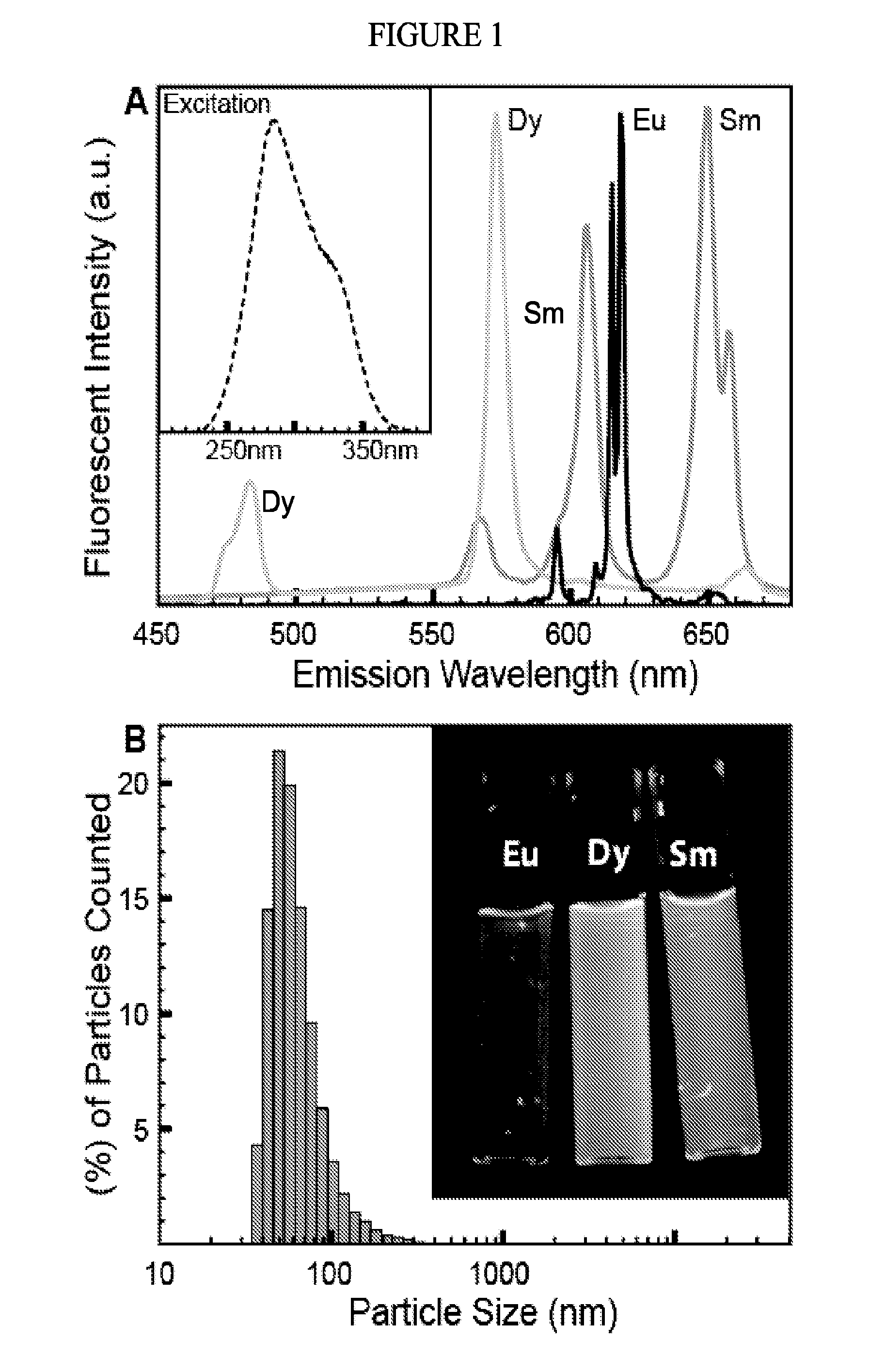
[0176]Nanoparticles for use in preparation of the disclosed spectrally encoded microbeads were synthesized using a polymer-assisted hydrothermal approach combined with microwave irradiation. Chemical reagents and polymers [poly(ethylene glycol) (PEG) and poly(acrylic acid) (PAA)] for nanoparticle synthesis were purchased from Sigma-Aldrich (St. Louis, Mo.) and were used without further purification. Microwave synthesis was performed using a Biotage Initiator (Biotage AB, Uppsala, Sweden). Purification of the synthesized nanoparticles was performed by ultrafiltration using Amicon Ultra-15 centrifugal filter units with a 50,000 Dalton Molecular Weight Cutoff (MWCO) (Millipore, Billerica, Mass.), resulting in suspensions with a nanoparticle concentration of ˜50 mg / mL in water. Luminescence spectra were measured using a FluoroMax-3 (Horiba Scientific, Kyoto, Japan) spectrofluorometer and the nanoparticle particle size distributions were measured usin...

example 2

Synthesis of Ratiometrically Encoded Polymeric Beads

[0179]Microfluidic Device Production

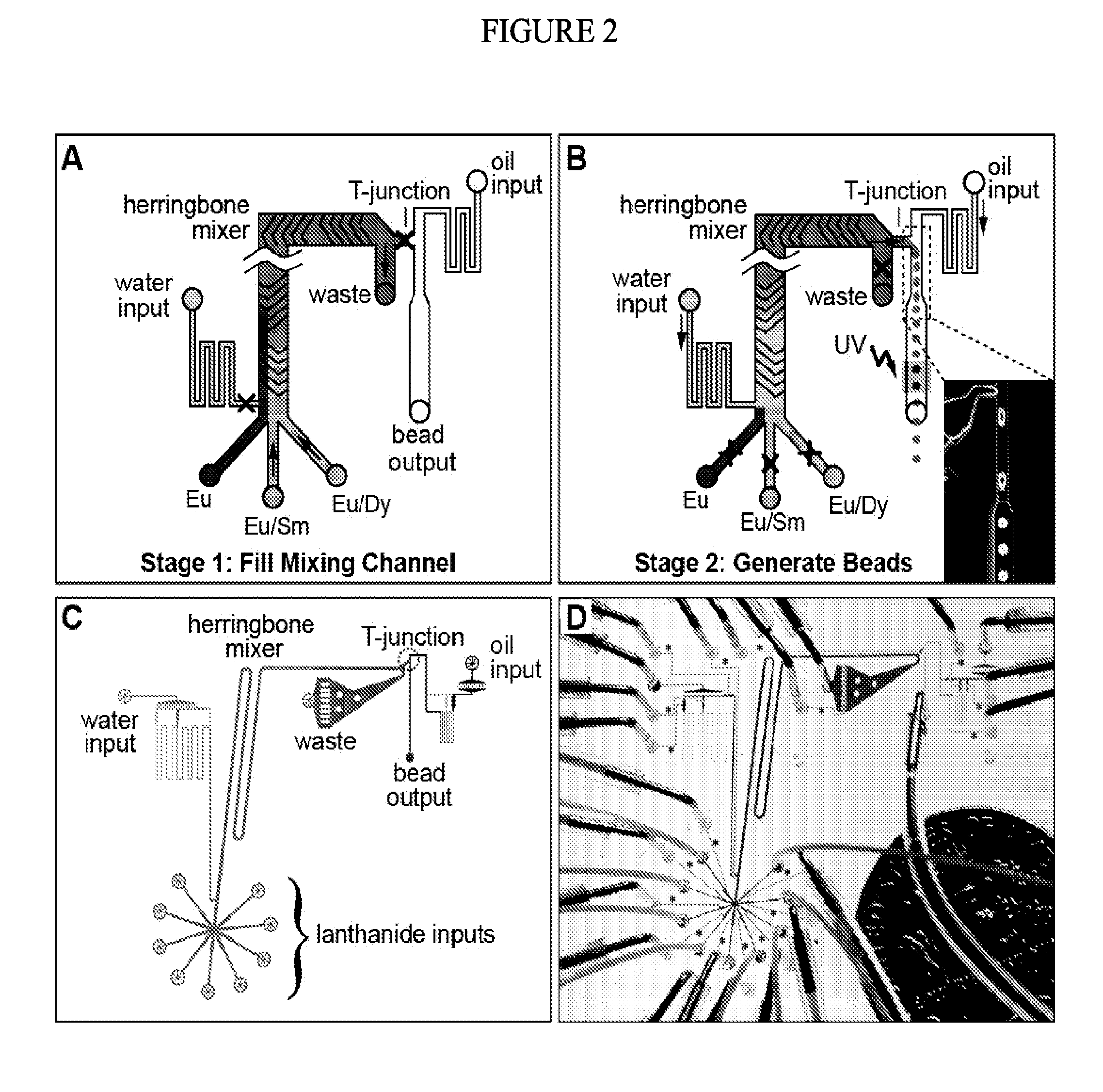
[0180]To incorporate the prepared lanthanide nanoparticles into solid beads at programmed ratios, a custom, fully-automated microfluidic device was designed and fabricated. Devices were fabricated in poly(dimethylsiloxane) (PDMS, RTV 615, Momentive Performance Materials, Albany, N.Y.) by Multi-Layer Soft Lithography using 4″ test-grade silicon wafers (University Wafer, South Boston, Mass.) coated with multiple layers of SU8 (Microchem Corp., Newton, Mass.) and AZ50 XT photoresists (Capitol Scientific, Austin, Tex.) patterned by standard photolithography processes.

[0181]All photolithography masks were designed using AutoCAD (Autodesk, San Rafael, Calif.) and printed onto transparency film with a resolution of 30,000 dpi (FineLine Imaging, Colorado Springs, Colo.). To improve adhesion of subsequent photoresist layers, all wafers were first coated with a 5 μm layer of SU-8 2005 negative photoresist ...

example 3

Imaging of Spectrally Encoded Beads

[0201]Microfluidic Device Production

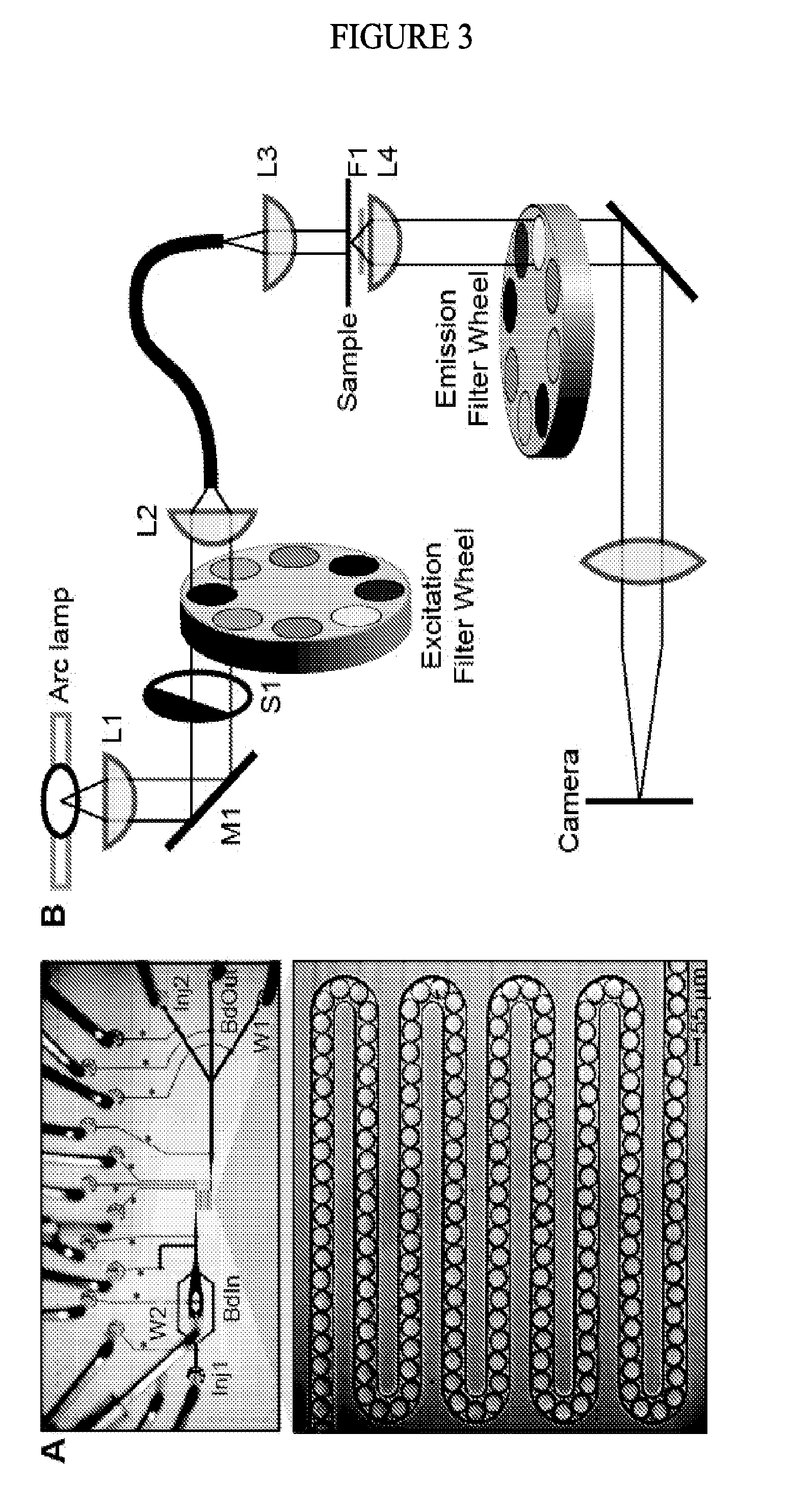
[0202]To measure the lanthanide luminescence ratios in the spectrally encoded beads, an additional custom microfluidic device was developed to create an ordered linear array of ˜190 beads within a narrow serpentine channel (FIG. 3, Panel A) covering a ˜1 mm2 area. Beads in the serpentine can be loaded and unloaded using on-chip valves in the fluidic circuit, allowing for efficient imaging of large numbers of beads.

[0203]All photolithography masks were designed using AutoCAD (Autodesk, San Rafael, Calif.) and printed onto transparency film with a resolution of 30,000 dpi (FineLine Imaging, Colorado Springs, Colo.). To improve adhesion of subsequent photoresist layers, all wafers were first coated with a 5 μm layer of SU-8 2005 negative photoresist (Microchem Corp.) according to the manufacturer's instructions. All spin-coating steps were performed on a G3P-8 programmable spin coater (Specialty Coating Systems, Ind...


PUM

PropertyMeasurementUnit
diameteraaaaaaaaaa
diameteraaaaaaaaaa
diameteraaaaaaaaaa

Abstract

Spectrally encoded microbeads and methods and devices for making and using spectrally encoded microbeads are provided. The disclosed methods and devices facilitate the preparation and use of microbeads containing multiple lanthanide nanoparticles, which microbeads have uniquely identifiable spectral codes. The disclosed microbeads, and the methods and devices for making and using same, find use in multiplexing and high-throughput biomarker analysis.

Description

CROSS-REFERENCE TO RELATED APPLICATIONS[0001]This application claims of benefit of U.S. Provisional Patent Application No. 61 / 692,618, filed Aug. 23, 2012, which application is incorporated herein by reference in its entirety.STATEMENT REGARDING FEDERALLY SPONSORED RESEARCH[0002]The invention was made with government support under Grant No. DE-AC02-05CH11231 awarded by the U.S. Department of Energy. The government has certain rights in the invention.INTRODUCTION[0003]Over the past several years, advances in biomedical research technology have driven an unprecedented explosion of genomic and proteomic data, yet the challenge of translating new biomarkers of disease into actionable diagnostics and therapeutics remains daunting. To both validate and deploy the vast numbers of recent discoveries into clinical practice requires new approaches to multiplexing and high-throughput biomarker analysis. Despite intense research, few practically available cost-effective assays for multiplexing ...

Claims


Application Information

Patent Timeline
Patent Type & Authority Applications(United States)
IPC IPC(8): G01N21/64
CPCG01N2201/061G01N21/64G01N33/585G01N33/587G01N2458/40B82Y30/00C08F2/44C08F222/385B01F23/45B01F23/41B01F25/43172B01F25/431971B01F33/3011B01F33/30B01F33/821B01F25/4317
Inventor BAXTER, BRIAN CULLENDERISI, JOSEPH L.FORDYCE, POLLY M.GERVER, RACHEL E.G MEZ-SJOBERG, RAFAELHELMS, BRETT A.THORN, KURT S.ZUCKERMANN, RONALD N.
Owner RGT UNIV OF CALIFORNIA
Learn More