
Method and system for compressed sensing image reconstruction

a sensing image and compressed technology, applied in the field of compressed sensing image reconstruction, can solve the problems of increasing the risk of developing cancer, reducing the detectability of lesions, and reducing the safety of incomplete scan data

Active Publication Date: 2015-07-02
UNIV HEALTH NETWORK
View PDF8 Cites 28 Cited by
  • Summary
  • Abstract
  • Description
  • Claims
  • Application Information

AI Technical Summary

Benefits of technology

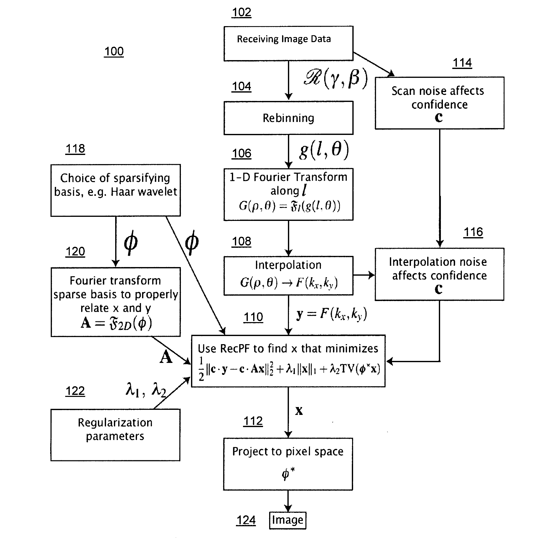
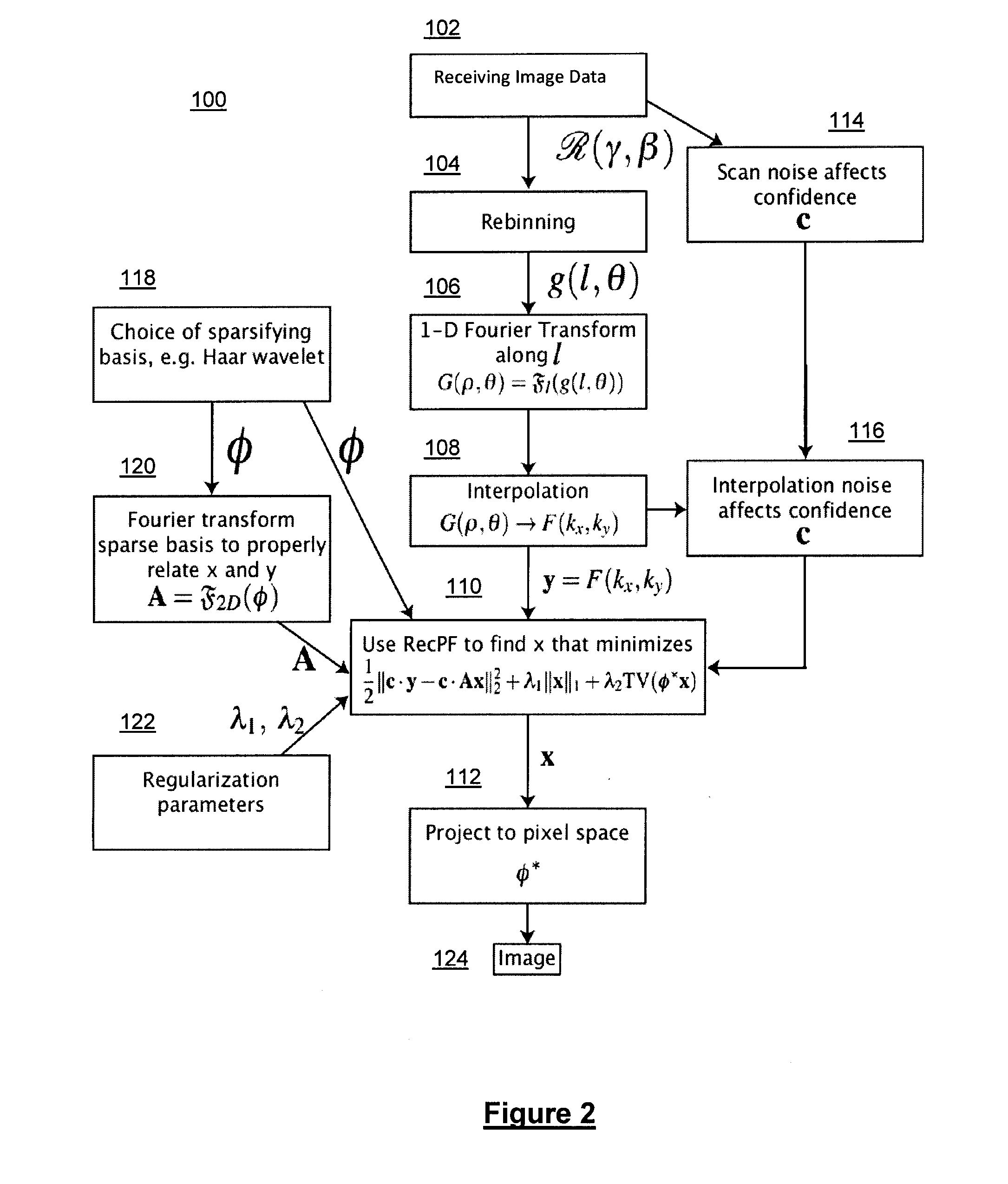
The present invention provides a method for image reconstruction by receiving signals representing a set of raw image data and performing a 1-dimensional Fourier transform to convert the data into the partial Fourier domain. An optimization model is determined to recover the original image data based on the transformed data and an inverse operation is performed to convert the data back into the image domain. The method can be used with different imaging modalities and can handle incomplete or overcomplete data. The recovered image data can be displayed on a screen or used for further analysis. The technical effects may include improved image resolution and accuracy, as well as faster and more efficient image reconstruction.

Problems solved by technology

However, CT scans may deliver a relatively large radiation dose to patients, giving rise to concerns that this may result in an increased risk of developing cancer.
Using a known image reconstruction algorithm, Filtered Back Projection (FBP), low dose CT images suffer from low contrast to noise ratio which decreases the detectability of the lesions.
Moreover, since the heart typically must be at rest while a cardiac CT scan is in progress, often only incomplete scan data may be safely available, especially in patients with an elevated heart rate.
Compressed sensing and its application to CT scanning has been demonstrated before in a variety of ways: iterative reconstruction methods have been found to reduce the noise effects in the low dose images somewhat, while compressed sensing may be prohibitively slow using current techniques.
Catheter coronary angiography (CCA) is the current “Gold Standard” for direct visualization of coronary artery patency, but it is typically an invasive and expensive procedure with associated morbidity and mortality (see for example, D. C. Levin, “Invasive evaluation (coronary arteriography) of the coronary artery disease patient: clinical, economic, and social issues,” Circulation, 1982; 66:71-9, T. J. Ryan, “The coronary angiogram and its seminal contributions to cardiovascular medicine over five decades,” Circulation, 2002; 106:752-6, the entire contents of each is hereby incorporated by reference) and the technique is typically limited to estimation of lumen patency.
However, there are patients who may experience an acute cardiac event, such as sudden cardiac death, with lesions that hitherto had been hemodynamically insignificant.
These lesions are thought to be susceptible to sheer stress, subsequent rupture and haemorrhage with conversion of a non-obstructive plaque into one causing significant luminal stenosis.
However, this is also typically an invasive, time intensive and expensive technique with limited patient access.
However, there may be one or more limitations in the use of current CT technology for accurate evaluation of coronary patency and plaque characterization, including in-plane temporal resolution, spatial resolution, contrast resolution, and radiation dose which may be addressed by embodiments described herein.
However, most available CS-based reconstruction techniques are either prohibitively computationally intensive using large discretized Radon transform matrix or make unphysical assumptions to avoid the polar to Cartesian domain conversion and accelerate the algorithm, which may be addressed by embodiments described herein.

Method used


Image

  • Method and system for compressed sensing image reconstruction
  • Method and system for compressed sensing image reconstruction
  • Method and system for compressed sensing image reconstruction

Examples


Embodiment Construction

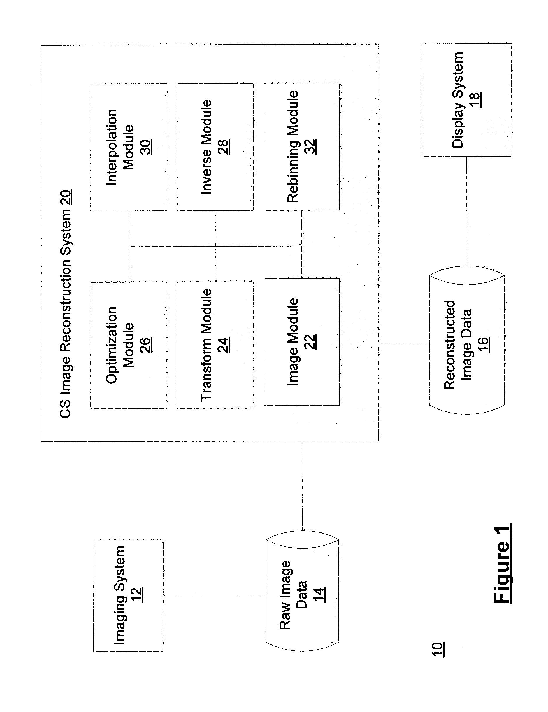
[0036]The embodiments of the systems and methods described herein may be implemented in hardware or software, or a combination of both. These embodiments may be implemented in computer programs executing on programmable computers, each computer including at least one processor, a data storage system (including volatile memory or non-volatile memory or other data storage elements or a combination thereof), and at least one communication interface. For example, and without limitation, the various programmable computers may be a server, network appliance, set-top box, embedded device, computer expansion module, personal computer, laptop, personal data assistant, cellular telephone, smartphone device, UMPC tablets and wireless hypermedia device or any other computing device capable of being configured to carry out the methods described herein.

[0037]Program code is applied to input data to perform the functions described herein and to generate output information. The output information i...


PUM


Abstract

A Compressed Sensing (CS) based image reconstruction method and system is described herein which may be used to reduce the X-ray dose radiation in Computed Tomography (CT) or to decrease the scan duration in MR imaging (MRI). Methods and systems described herein may address problems that have hindered the clinical usage of CS, i.e. computation complexity and modeling problems. Using the described algorithm, high quality images may be recovered from undersampled data which may help to reduce the scan time and the exposed invasive radiations. Using the same set of data in conventional image reconstruction algorithms (e.g. Filtered Back Projection (FBP) in CT) may cause severe streak artifacts and may take significantly more time using Graphics Processing Units (GPU) and parallel clusters with the conventional CS-based methods. This method can be used other imaging modalities using Radon transform (such as C-Arm and electron tomography, for example).

Description

FIELD OF THE INVENTION[0001]The present disclosure relates to methods and systems for compressed sensing image reconstruction. In particular, the present disclosure relates to methods and systems suitable for use in medical imaging reconstruction, such as in computed tomography (CT), magnetic resonance imaging (MRI), c-arm scanning, electron tomography, and other imaging modalities.INTRODUCTION[0002]CT utilization has increased dramatically over the last two decades; principally due to the unsurpassed speed and detail with which cross sectional views of soft tissue and organs can be obtained. However, CT scans may deliver a relatively large radiation dose to patients, giving rise to concerns that this may result in an increased risk of developing cancer. Using a known image reconstruction algorithm, Filtered Back Projection (FBP), low dose CT images suffer from low contrast to noise ratio which decreases the detectability of the lesions. As a result, a low dose CT scan technique tha...

Claims


Application Information

Patent Timeline
Patent Type & Authority Applications(United States)
IPC IPC(8): G06T5/00G06T7/00
CPCG06T7/0012G06T5/001A61B6/03A61B6/501A61B6/5205A61B5/055G01R33/5611G06T11/006G06T2211/424G06T2211/436H04N25/00G06T5/00
Inventor AMROABADI, SAYED MASOUD HASHEMIGILL, PATRICK R.PAUL, NARINDER S.
Owner UNIV HEALTH NETWORK
Learn More