
Measurement Of Multiple Patterning Parameters

Active Publication Date: 2015-06-25
KLA TENCOR CORP
View PDF9 Cites 42 Cited by
  • Summary
  • Abstract
  • Description
  • Claims
  • Application Information

AI Technical Summary

Benefits of technology

The patent text describes a method to improve the accuracy of measuring parameters in a combined measurement model. This is achieved by locating metrology targets as close together as possible, which reduces the likelihood of errors in the measurements. Additionally, the metrology targets are designed with a relatively large variation in pitch to enhance sensitivity for measuring light diffracted at a single order or multiple orders different from zero order. These technical effects improve the accuracy and efficiency of the measurement process.

Problems solved by technology

Ideally, the nominal pitch of the double patterned structure should be a constant value, P. However, due to imperfections in the DPL process, the pitch of the resulting structure may vary depending on location due to grating non-uniformities.
Similarly, although a double patterning process is described with reference to FIGS. 1A-1D, similar errors arise in higher order patterning processes such as quadruple patterning.
Typically, errors such as pitch walk and ΔCD are more pronounced in structures that result from higher order patterning processes.
However, measurement of errors induced by multiple patterning processes is especially challenging due to the fact that optical CD, and even CD-SEM measurements, lack significant sensitivity to these types of errors.
Metrology applications involving the measurement of structures generated by multiple patterning processes present challenges due to increasingly small resolution requirements, multi-parameter correlation, increasingly complex geometric structures, and increasing use of opaque materials.

Method used


Image

  • Measurement Of Multiple Patterning Parameters
  • Measurement Of Multiple Patterning Parameters
  • Measurement Of Multiple Patterning Parameters

Examples


Embodiment Construction

[0046]Reference will now be made in detail to background examples and some embodiments of the invention, examples of which are illustrated in the accompanying drawings.

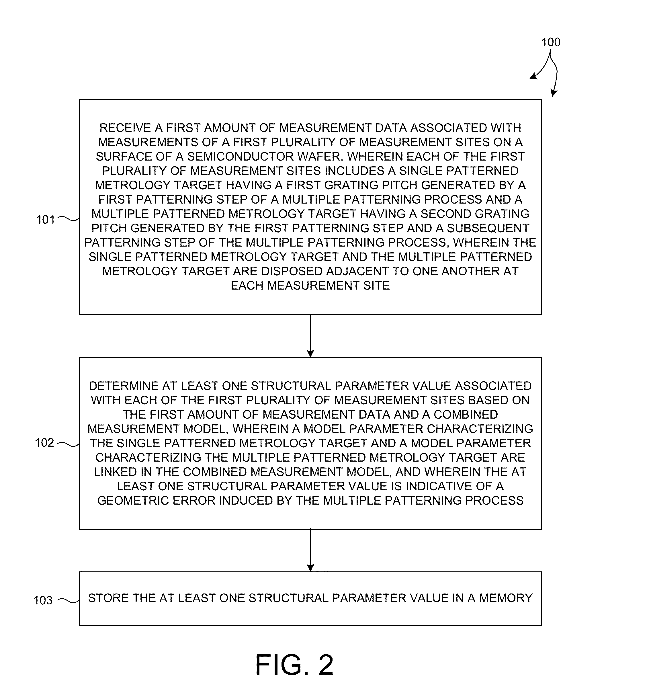
[0047]Methods and systems for evaluating the performance of multiple patterning processes are presented. More specifically, geometric structures generated by multiple patterning processes are measured and one or more parameter values characterizing geometric errors induced by the multiple patterning process are determined in accordance with the methods and systems described herein.

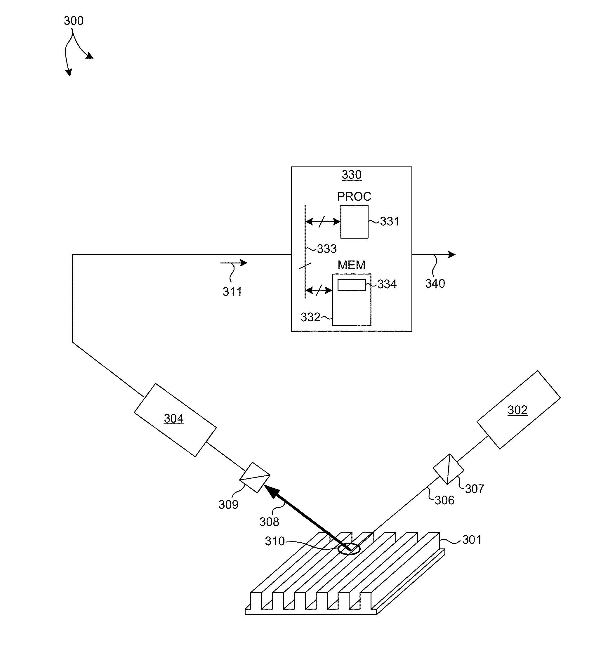
[0048]In one aspect, the value of a structural parameter indicative of a geometric error induced by the multiple patterning process is determined based on the measurement data and a combined measurement model. The measurement data is collected from a number of measurement sites on the surface of a semiconductor wafer. Each measurement site includes at least two metrology targets. The first metrology target is a single patterned metrology tar...


PUM


Abstract

Methods and systems for evaluating the performance of multiple patterning processes are presented. Patterned structures are measured and one or more parameter values characterizing geometric errors induced by the multiple patterning process are determined. In some examples, a single patterned target and a multiple patterned target are measured, the collected data fit to a combined measurement model, and the value of a structural parameter indicative of a geometric error induced by the multiple patterning process is determined based on the fit. In some other examples, light having a diffraction order different from zero is collected and analyzed to determine the value of a structural parameter that is indicative of a geometric error induced by a multiple patterning process. In some embodiments, a single diffraction order different from zero is collected. In some examples, a metrology target is designed to enhance light diffracted at an order different from zero.

Description

CROSS REFERENCE TO RELATED APPLICATION[0001]The present application for patent claims priority under 35 U.S.C. §119 from U.S. provisional patent application Ser. No. 61 / 920,462, entitled “Method and Apparatus for Measuring Parameters of Multiple Patterning,” filed Dec. 23, 2013, the subject matter of which is incorporated herein by reference in its entirety.TECHNICAL FIELD[0002]The described embodiments relate to metrology systems and methods, and more particularly to methods and systems for improved measurement of parameters characterizing the dimensions of structures generated by multiple patterning processes.BACKGROUND INFORMATION[0003]Semiconductor devices such as logic and memory devices are typically fabricated by a sequence of processing steps applied to a specimen. The various features and multiple structural levels of the semiconductor devices are formed by these processing steps. For example, lithography among others is one semiconductor fabrication process that involves g...

Claims


Application Information

Patent Timeline
IPC IPC(8): G01B11/27
CPCG01B11/27G01B11/272G03F7/70141H01L22/12H01L22/30G01B2210/56G03F7/70625G03F7/0002
Inventor SHCHEGROV, ANDREI V.KRISHNAN, SHANKARPETERLINZ, KEVINDZIURA, THADDEUS GERARDSAPIENS, NOAMPANDEV, STILIAN IVANOV
Owner KLA TENCOR CORP
Learn More