
Multispectral camera using zero-mode channel

Active Publication Date: 2015-06-04
RAYTHEON CANADA LTD
View PDF3 Cites 13 Cited by
  • Summary
  • Abstract
  • Description
  • Claims
  • Application Information

AI Technical Summary

Benefits of technology

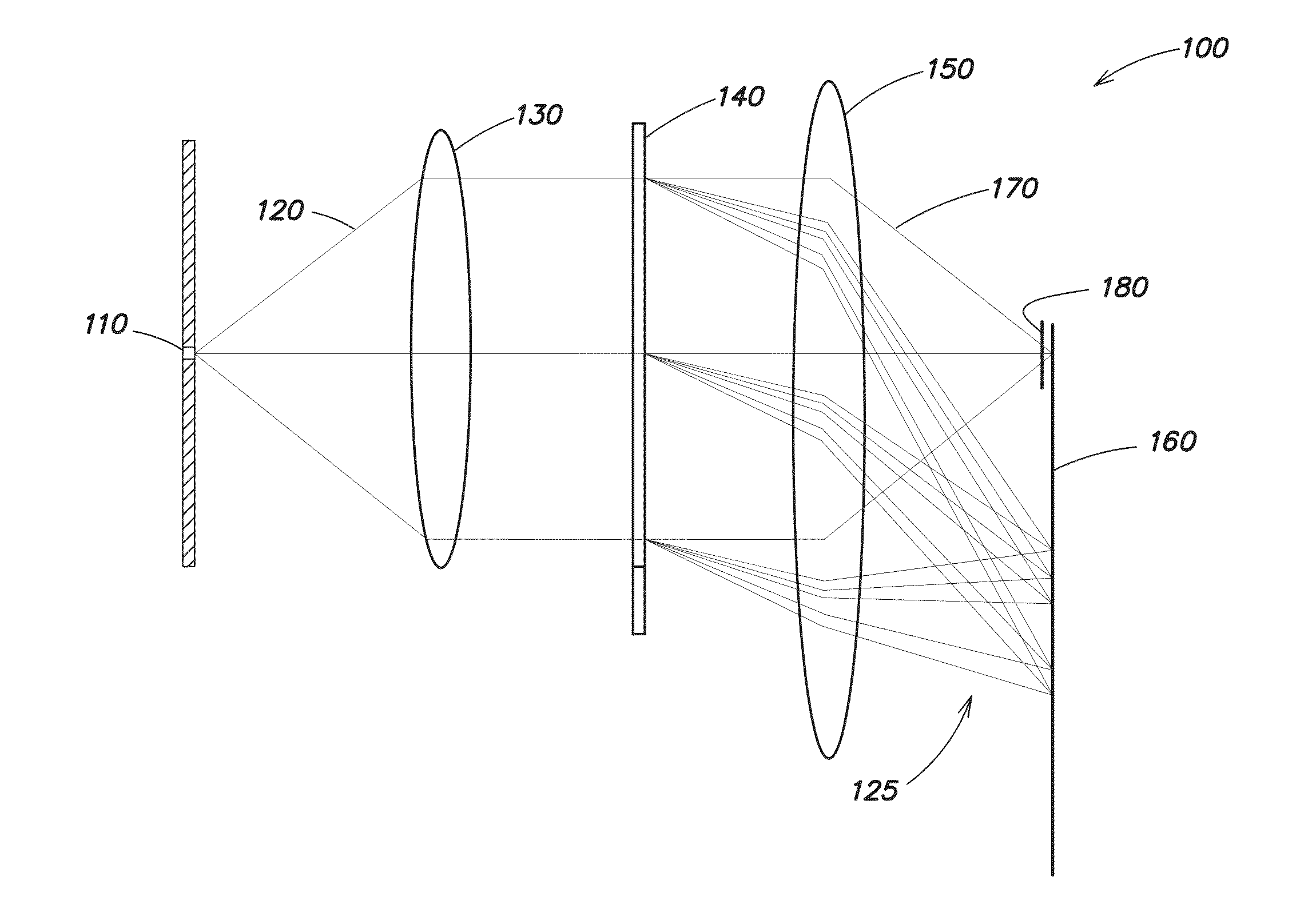
The patent describes a system and method for detecting other useful optical properties in addition to traditional spectral imaging data. The system uses a dispersive element to spectrally disperse and detect non-dispersed electromagnetic radiation, allowing for the detection of polarization and translucence scattering. The system includes a slit for receiving the electromagnetic radiation, a dispersive element, a focusing optic, and a filter to transmit the non-dispersed radiation to an imaging detector. The method involves receiving the electromagnetic radiation, spectrally dispersing it with the dispersive element to produce non-dispersed radiation, and imaging both the non-dispersed and spectrally dispersed radiation to produce a spectral and zero-mode image. The technical effects of this system and method include improved detection of optical properties and improved imaging quality.

Problems solved by technology

Although hyperspectral cameras provide useful spectral imaging data, conventional instruments lack the ability to meaningfully detect other useful optical information, such as polarization or translucence scattering, for example.

Method used


Image

  • Multispectral camera using zero-mode channel
  • Multispectral camera using zero-mode channel
  • Multispectral camera using zero-mode channel

Examples


Embodiment Construction

[0015]Aspects and embodiments are directed to a multispectral imaging system that is configured to produce both a conventional three-dimensional multispectral data cube and data related to additional optical properties (such as polarization and translucence, for example) by using the zero-mode channel which is typically ignored in conventional multispectral imagers. As used herein, the term multispectral imager is intended to include both multispectral and multispectral imagers. As discussed in more detail below, according to certain embodiments, a filter is positioned in the optical train of a multispectral imaging system and configured to pass the zero-mode channel to an imaging detector located at the image plane of the system. The filter may have any of numerous configurations, depending, for example, on the optical property to be measured using the zero-mode channel. Using this approach, a multispectral imaging system may be readily configured to provide additional information ...


PUM


Abstract

A multispectral imaging system and method in which the zero-mode channel is used to provide imaging of any of a variety of optical properties. In one example an imaging method includes spectrally dispersing received electromagnetic radiation into its spectral components with a dispersive element to produce spectrally dispersed electromagnetic radiation, transmitting the electromagnetic radiation through the dispersive element to produce non-dispersed electromagnetic radiation corresponding to a zero order diffraction mode of the dispersive element, imaging the non-dispersed electromagnetic radiation to produce a zero-mode image, and simultaneously imaging the spectrally dispersed electromagnetic radiation to produce a spectral image.

Description

BACKGROUND[0001]Hyperspectral cameras are used to detect and analyze the spectral composition of electromagnetic radiation, generally in near ultraviolet, visible, and infrared spectral bands of electromagnetic radiation. Hyperspectral sensors collect information as a set of “images.” Each image in the set represents a range of the electromagnetic spectrum referred to as a spectral band. These “images” are combined to form a three-dimensional hyperspectral data cube for processing and analysis. Hyperspectral remote sensing is used in a wide array of applications.[0002]Conventional multispectral imaging systems rely on linear detectors and mirrors or platform motion to move an image across the sensor to capture and record multispectral images. A multispectral image is one that captures image data at specific frequencies across the electromagnetic spectrum. For different purposes, different combinations of spectral bands can be used. Systems relying on scanning mirrors to obtain multi...

Claims


Application Information

Patent Timeline
IPC IPC(8): H04N5/232G02B5/20G02B5/30
CPCH04N5/23212G02B5/20G02B5/30G01J3/0224G01J3/18G01J3/2823G01J2003/1213G02B13/14G02B27/285G01J3/0229G01J3/24G01J3/447G01N21/4738
Inventor DENIS, DONALD J.
Owner RAYTHEON CANADA LTD
Learn More