
Pattern evaluation device and pattern evaluation method

Inactive Publication Date: 2015-05-28
HITACHI HIGH-TECH CORP
View PDF16 Cites 12 Cited by
  • Summary
  • Abstract
  • Description
  • Claims
  • Application Information

AI Technical Summary

Benefits of technology

The present invention is about a machine and method that checks the patterns of circuits. The invention helps to quickly inspect and approve the patterns, which increases efficiency and productivity.

Problems solved by technology

Conventionally, the image capture recipe has been manually created by an operator, which is a task requiring much effort and time.

Method used


Image

  • Pattern evaluation device and pattern evaluation method
  • Pattern evaluation device and pattern evaluation method
  • Pattern evaluation device and pattern evaluation method

Examples


Embodiment Construction

[0029]The present invention provides, in design or manufacturing procedures of a semiconductor device, an apparatus and method for efficiently inspecting a disconnection or a shape defect in circuit patterns formed on a wafer, which can cause electrical failures, by imaging the circuit patterns with a scanning charged particle microscope which is an image capturing device. Although embodiments according to the present invention will be described hereinafter in respect of a scanning electron microscope (SEM), which is one of the scanning charged particle microscopes, the present invention is not limited to the SEM, but is applicable to other scanning charged particle microscopes such as a scanning ion microscope (SIM). Further, the present invention is not limited to inspection of the semiconductor device, but is applicable to inspection of samples having patterns required to be imaged and evaluated.

1. Image Capturing Device

1.1 SEM Components

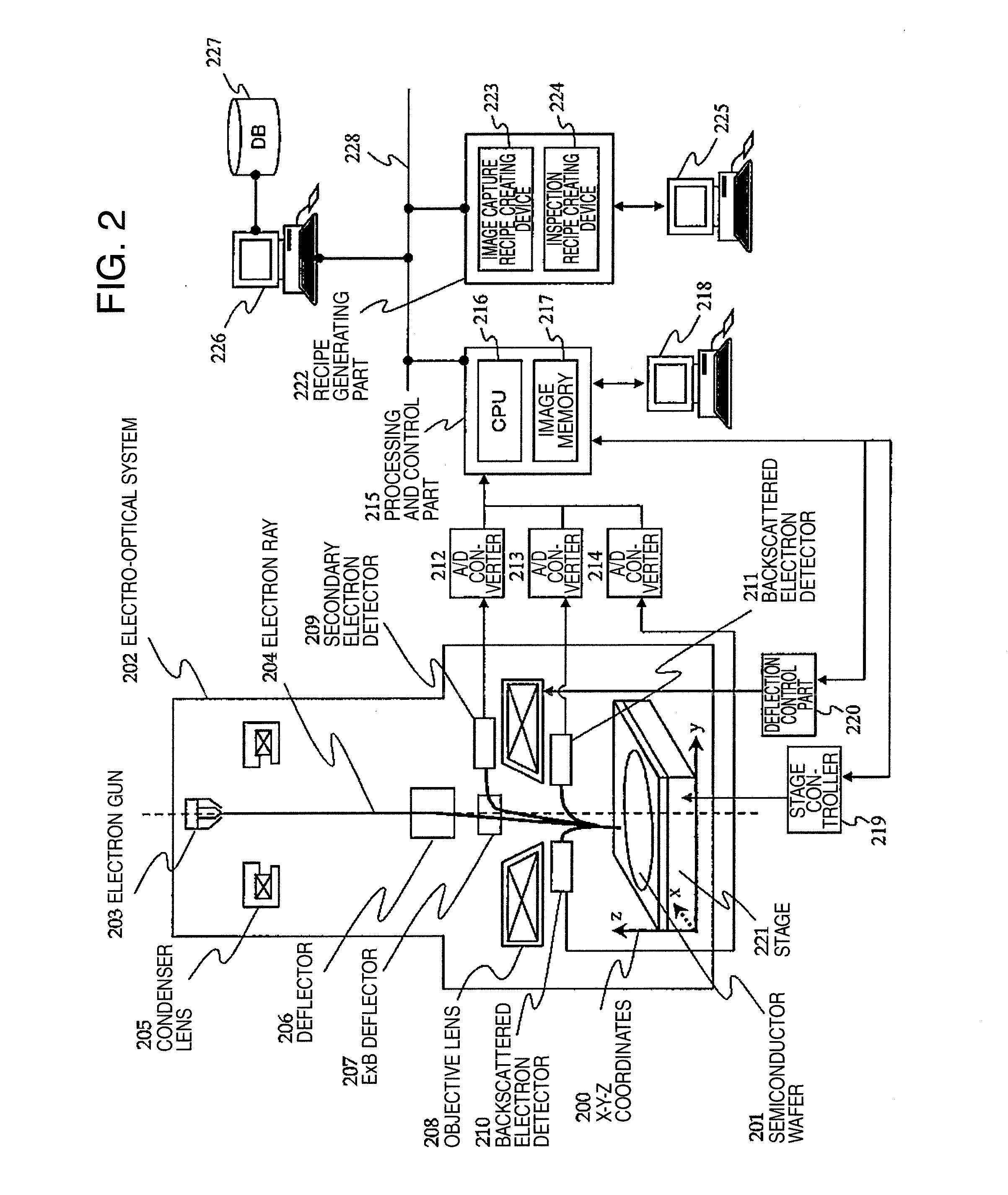
[0030]FIG. 2 shows an example of an inspec...


PUM


Abstract

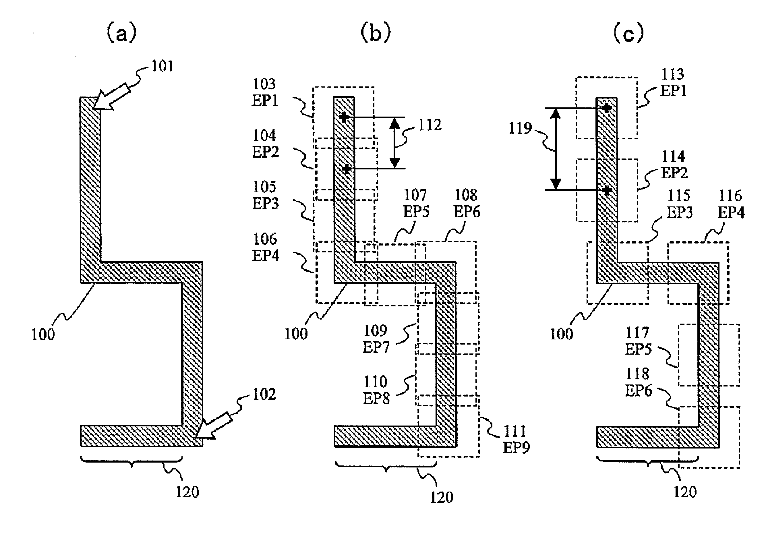
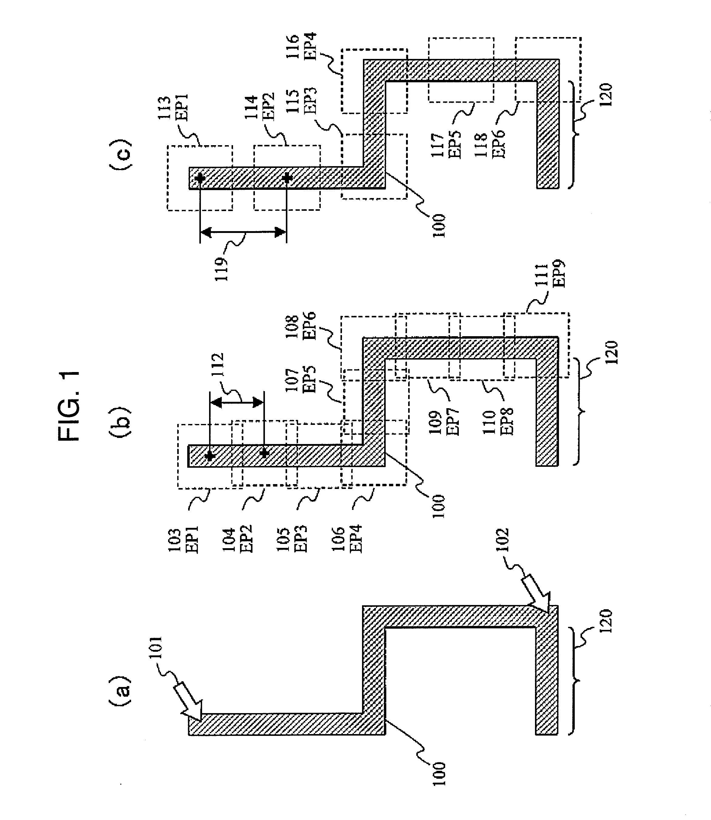
The present invention relates to a setting method for an image capture area on the occasion of evaluation of a circuit pattern using a scanning charged particle microscope. A circuit pattern that is to be evaluated using an actual image or design data is determined, a plurality of image capture areas are set such that the circuit pattern to be evaluated is included in a section of the field of vision, and images are captured of the plurality of image capture areas. When setting the image capture areas, a permissible value for the distance between adjacent first and second images is set, and the positions of the image capture areas are optimized so as to correspond as closely as possible with the permissible value for distance. As a result, it is possible to improve the throughput of image capture of wide inspection areas that do not fit in the field of vision of the scanning charge particle microscope, and to efficiently carry out determination of an inspection area that may cause electrical failure.

Description

TECHNICAL FIELD[0001]The present invention relates to a method and apparatus for effectively inspecting a circuit pattern with a scanning charged particle microscope.BACKGROUND ART[0002]In forming a circuit pattern on a semiconductor wafer, there is employed a method for forming a circuit pattern by applying a coating material (referred to as a resist) on the semiconductor wafer, stacking a mask (a reticle) for exposure of the circuit pattern on the resist and irradiating a visible ray, an ultra violet ray or an electron beam thereon to expose and develop the resist in order to form a circuit pattern of the resist on the semiconductor wafer, and further etching the semiconductor wafer with the circuit pattern of the resist as a mask, for example.[0003]In design and manufacturing of semiconductor devices, it is important to manage dust emission in manufacturing devices such as exposing and etching devices, and to evaluate the shape of the circuit pattern formed on the wafer. Because ...

Claims


Application Information

Patent Timeline
IPC IPC(8): G06T7/00G06T3/40G02B21/36
CPCG06T7/001G02B21/365G06T2207/10056G06T2207/30141G06T3/40G02B21/367G06T2207/30148H01J37/22H01J37/28H01J2237/24592H01J2237/2817H01L22/12H01L2924/0002H01L2924/00G01B15/04G01N23/225G06T1/00H01L21/67
Inventor MIYAMOTO, ATSUSHIKAWAHARA, TOSHIKAZUONIZAWA, AKIHIROHOJO, YUTAKA
Owner HITACHI HIGH-TECH CORP
Learn More