Conduit connection apparatus with purge gas

Inactive Publication Date: 2015-05-21
HATCH LTD
View PDF5 Cites 9 Cited by
  • Summary
  • Abstract
  • Description
  • Claims
  • Application Information

AI Technical Summary

Benefits of technology

The patent text describes a method of connecting two conduits to prevent fluid from escaping or entering the environment. This is achieved by using a flow of purge gas that creates a pressure gradient to prevent fluid egress or ingress. The technical effect of this method is to provide a reliable and effective connection between two conduits while preventing fluid leakage.

Problems solved by technology

In general, it may be difficult to achieve a gas-tight seal for flange joints in high temperature applications, as the gaskets and other flange components may be subject to wear and damage due to thermal expansion.

Method used


Image

  • Conduit connection apparatus with purge gas
  • Conduit connection apparatus with purge gas
  • Conduit connection apparatus with purge gas

Examples


Embodiment Construction

[0028]In the following description, specific details are set out to provide examples of the claimed subject matter. However, the examples described below are not intended to define or limit the claimed subject matter. It will be apparent to those skilled in the art that many variations of the specific examples may be possible within the scope of the claimed subject matter.

[0029]For simplicity and clarity of illustration, where considered appropriate, reference numerals may be repeated among the drawings to indicate corresponding or analogous elements or steps.

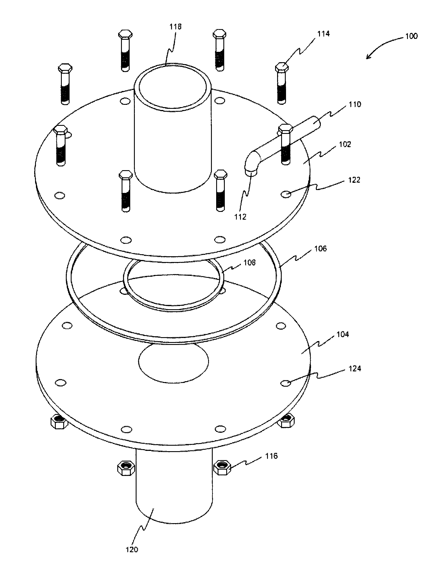
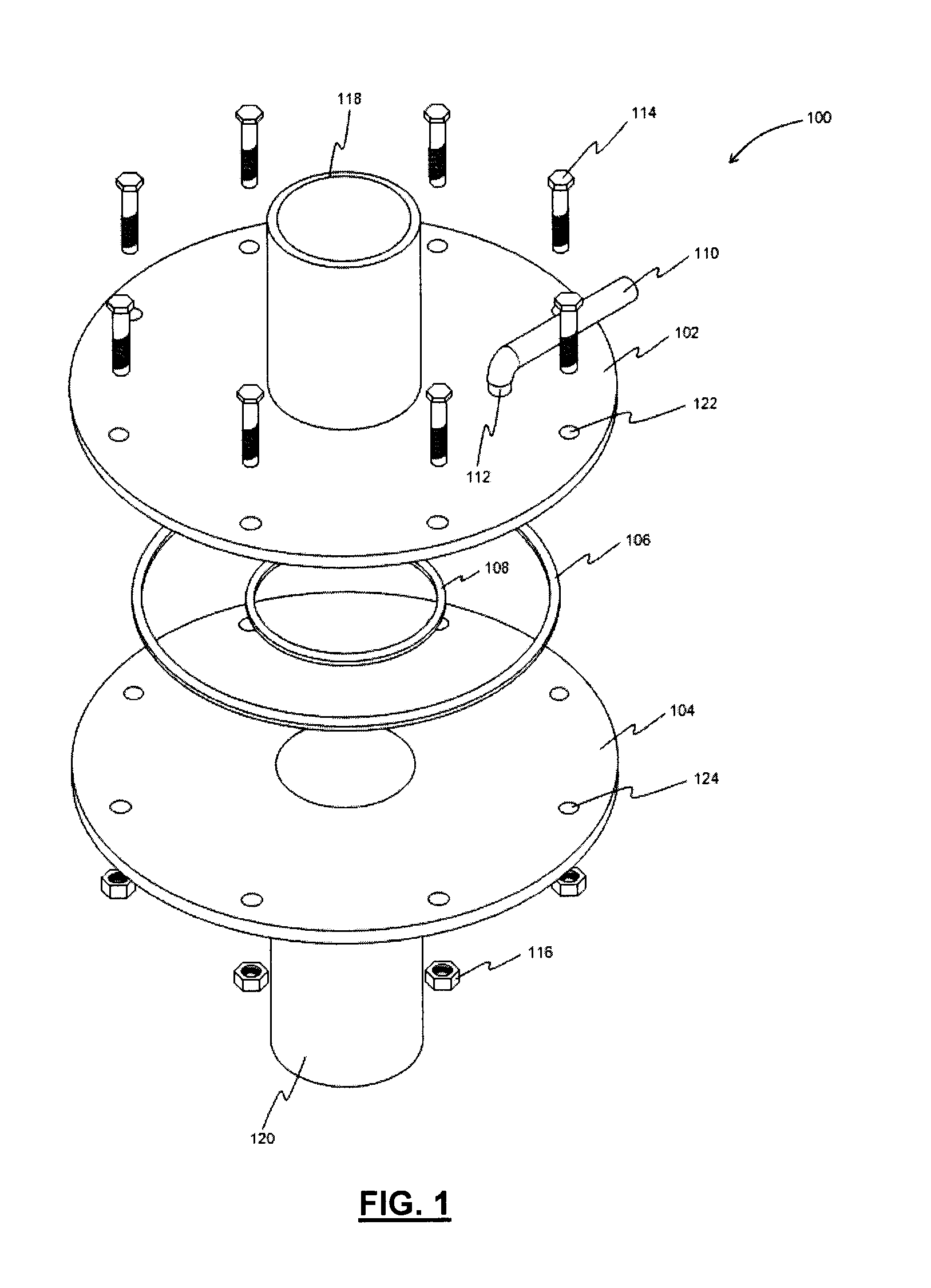
[0030]Referring to FIG. 1, an example of a conduit connection apparatus is shown generally at reference numeral 100. In the example illustrated, the apparatus 100 includes a first flange element 102, a second flange element 104, an outer gasket 106, an inner gasket 108, a purge gas supply line 110, a connection nipple 112, a plurality of bolts 114, and a plurality of nuts 116.

[0031]The first flange element 102 is welded or othe...


PUM


Abstract

An apparatus connects first and second conduits that convey a flow of gas. The apparatus includes a first flange element fixed to the first conduit, and a second flange element fixed to the second conduit. The flange elements are coupled together to permit fluid communication in an internal environment between the first and second conduits. At least one port is intermediate the flange elements to deliver a flow of purge gas therebetween. The at least one port may be located within a purge gas channel arranged in one of the flange elements. A pressure gradient of the flow of purge gas may substantially prevent at least one of fluid egress from the internal environment and fluid ingress from an external environment. Purge gas distribution systems and related methods are also described.

Description

TECHNICAL FIELD[0001]The present disclosure relates to sealing of conduits, such as pipe or duct connections, and to gas purging to establish a pressure gradient that prevents fluid egress and ingress.BACKGROUND[0002]The following paragraphs are not an admission that anything discussed in them is prior art or part of the knowledge of persons skilled in the art.[0003]Industrial processes involving gas flows may employ flange joints to connect individual pipe or duct segments. Flange joints may achieve a gas-tight seal by compressing a gasket between their mating surfaces, in order to fill any surface irregularities. In facilities involving flammable and / or poisonous process gases, preserving a gas-tight seal is important to avoid equipment damage and ensure safety.[0004]For example, in a calcium carbide smelter, carbon monoxide off-gas may be ducted through a gas handling system for cooling, cleaning, and / or storage of the off-gas. Such a gas handling system may include numerous flan...

Claims


Application Information

Patent Timeline
IPC IPC(8): F16L23/18B08B9/032
CPCB08B9/0325F16L23/18F16L23/167G01M3/2853F16L2201/30Y10T137/0419Y10T137/4259
Inventor TROVANT, MICHAELHAQUE, MIRZA RIDWANULAL-DOJAYLI, MAHERJOKOVIC, PREDRAGGHORBANI, HAMIDREZABHAVSAR, SANDEEP SURYAKANTMADIC, BOSKO
Owner HATCH LTD
Why Eureka
Try Eureka