
Tangential discharge disk refiner

a technology of tangential discharge and refiner, which is applied in the field of refiners, can solve the problems of poor bond formation and limited paper made of raw fibers, and achieve the effect of improving the overall performance and facilitating the hydrodynamic balance of the rotor

Inactive Publication Date: 2007-06-12
OVIVO LUXEMBOURG R L
View PDF13 Cites 6 Cited by
  • Summary
  • Abstract
  • Description
  • Claims
  • Application Information

AI Technical Summary

Benefits of technology

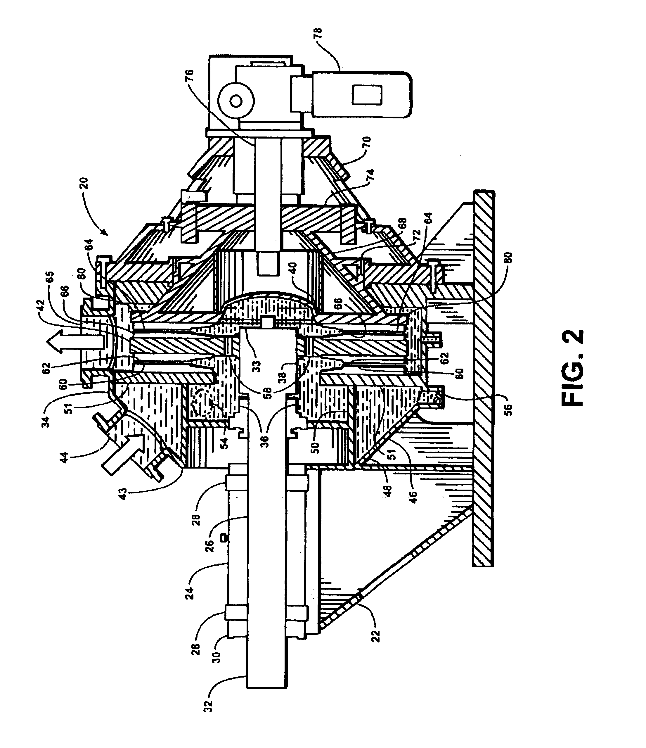
[0010]The disk refiner of this invention improves the overall performance of a twin disk refiner of the type having two stationery disks and a single rotor on which are mounted opposed refiner disks which oppose the stationery disks. As is conventional, one of the stationary disks is fixed and the other is mounted for axial movement towards the other stationery disk. In the past the shaft on which the rotor was mounted was movable axially to position the rotor between the stationery disks as the distance between the stationery disks was adjusted. In the disk refiner of this invention the rotor is mounted for axial movement to a spline. The spline forms part of a drive shaft connected to a drive motor. The spline mounting facilitates hydrodynamic balance of the rotor between the stationary disks.
[0011]The disk refiner supports the stationery disks on less rigid structure but is designed to allow stock to circulate on both sides of the disk support structure. This improves alignment between the rotor mounted refiner disks and the stationary refiner desks in two ways: by balancing fluid pressures on both sides of the stationery mounting structures for the refiner disks, and by preventing thermal gradients from causing deflection of these same structures.
[0012]In order to prevent damage to the refiner plates due to tramp metal, the incoming stock is centrifugally accelerated in a shroud which separates and traps tramp metal or the like before the stock passes between the stationery and rotating refiner disks. The shroud has passageways which allow the rotating fluid to enter a reservoir which surrounds the drive shaft and feeds the gaps between the rotor and the stationary plates. By pre-rotating the stock before it flows to the rotor, stock is more easily balanced between both sides of the rotor because the rotating stock can pass through openings in the rotor to reach the rotor back side.
[0013]It is a feature of the present invention to provide a disk refiner with reduced wear of the refiner plates.
[0016]It is a yet further feature of the present invention to provide a lighter weight refiner which supports with less deflection the stationary refiner plates.
[0017]It is another further feature of the present invention to provide a double disk refiner with lower maintenance cost.

Problems solved by technology

Raw fibers are relatively stiff and have relatively low surface area when the primary wall is intact, and thus raw fibers exhibit poor bond formation, with the result that paper which is made of raw fibers has limited strength

Method used


Image

  • Tangential discharge disk refiner
  • Tangential discharge disk refiner
  • Tangential discharge disk refiner

Examples


Embodiment Construction

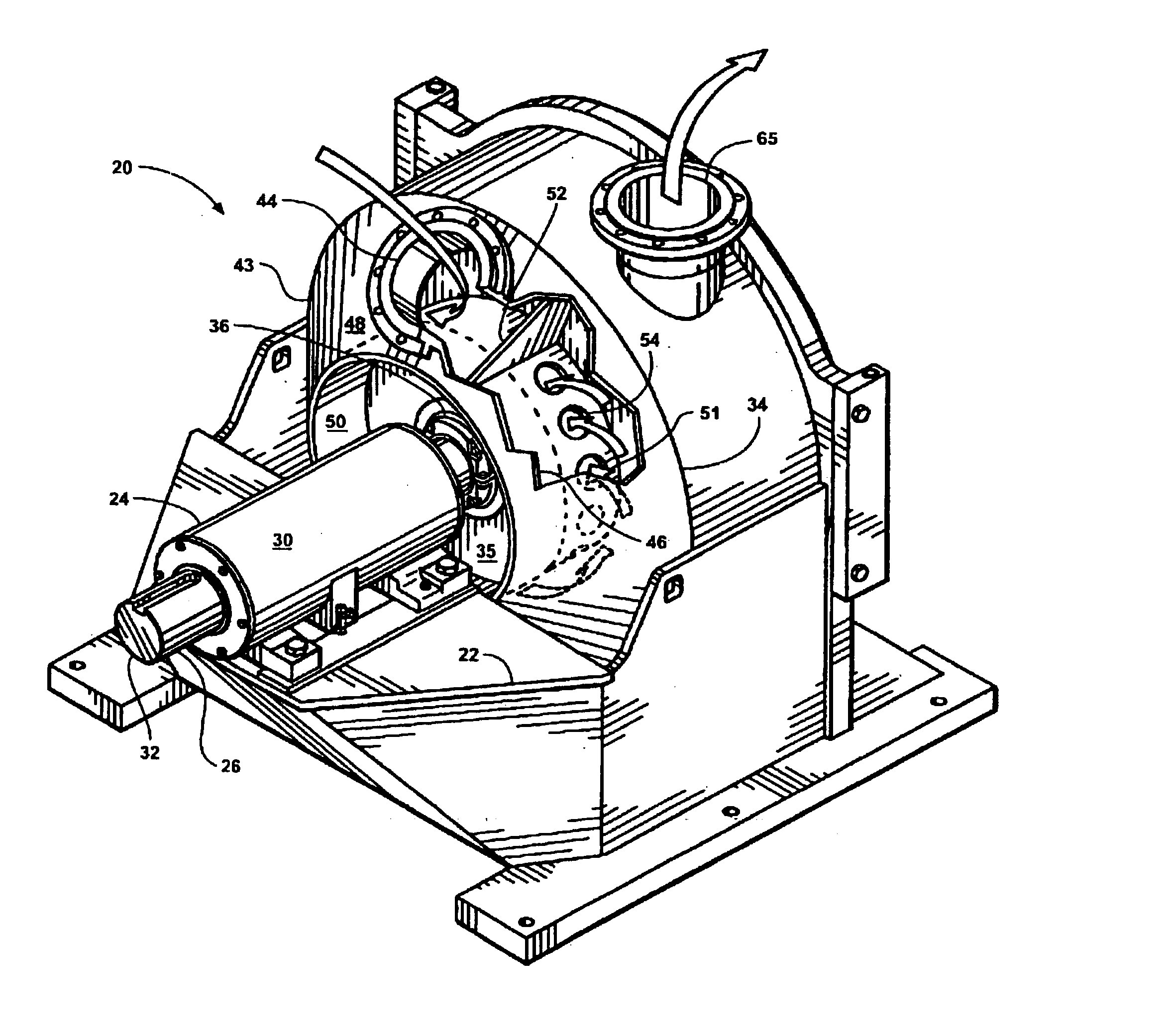
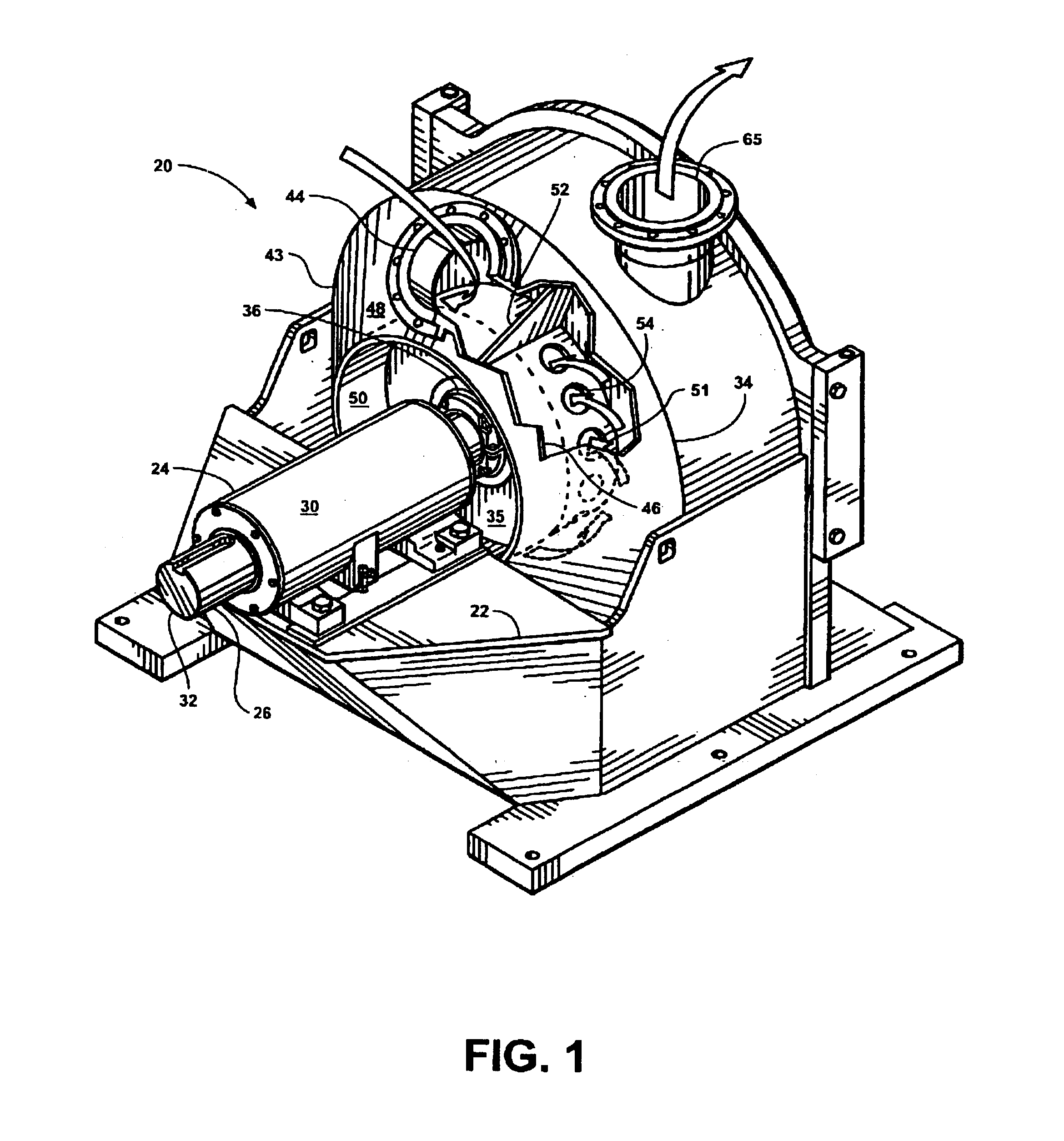
[0022]Referring more particularly to FIGS. 1-3 wherein like numbers refer to similar parts, a double disk refiner 20 is shown in FIGS. 1-3. The refiner 20 has a machine frame 22 on which is mounted a rotating assembly 24 having a shaft 26 mounted by bearings 28 to a shaft case 30. The shaft 26 is connected at a first end 32 to a drive motor (not shown). A second end 33 of the shaft 26 passes into a refiner housing 34 through a circular bulkhead 35 at a removable packing box 36. As shown in FIG. 2, the second shaft end 33 is machined to form a spline 38 to which the hub 40 of a rotor 42 is mounted.

[0023]The drive side 43 of the refiner housing 34 has a stock inlet 44 which supplies stock to a shroud 46 defining a triangular cross-section passageway between an outer conical shell 48, an inner cylindrical structure 50, and a drive side stationery plate support structure 51. The inner cylindrical structure 50 surrounds the bulkhead 35. The shroud 46 causes the stock to rotate producing ...


PUM

PropertyMeasurementUnit
thicknessaaaaaaaaaa
thicknessaaaaaaaaaa
diameteraaaaaaaaaa

Abstract

A papermaking refiner has two stationary disks mounted to the support structure of a fixed housing. A rotating disk is mounted on a shaft which extends through the housing. The support structure allows stock to circulate on both sides of the disk support structure, thus balancing fluid pressures on both sides of the fixed disk and preventing thermal gradients for reduced deflection of the disks. The incoming stock is centrifugally accelerated in a shroud which separates and traps tramp metal or the like before the stock passes to the refiner disks. The shroud has passageways which allow the rotating fluid to enter a reservoir which surrounds the drive shaft and feeds the gaps between the rotor and the stationary plates.

Description

CROSS REFERENCES TO RELATED APPLICATIONSSTATEMENT AS TO RIGHTS TO INVENTION MADE UNDER FEDERALLY SPONSORED RESEARCH AND DEVELOPMENTBACKGROUND OF THE INVENTION[0001]The present invention relates in general to refiners for treating paper pulp fibers to condition the fibers prior to delivery to a papermaking machine and to refiners for handling stock having a consistency of about 3 to about 6 percent fiber by weight.[0002]Disc refiners are used in the papermaking industry to prepare paper pulp fibers for the forming of paper on a papermaking machine.[0003]Paper stock containing three to six percent dry weight fibers is fed between closely opposed rotating discs within the refiner. The refiner discs perform an abrading operation on the paper fibers as they transit radially between the opposed moving and non-moving refiner discs. The purpose of a disc refiner is to abrade the individual wood pulp fibers.[0004]Processing of fibers in a low consistency refiner may be performed on both chem...

Claims


Application Information

Patent Timeline
Patent Type & Authority Patents(United States)
IPC IPC(8): B02C7/02B02C7/06D21D1/30
CPCB02C7/06D21D1/303
Inventor LARIVIERE, CHRISTOPHER J.
Owner OVIVO LUXEMBOURG R L
Learn More