Premixing burner for generating an ignitable fuel/air mixture

a technology of ignitable fuel and air mixture, which is applied in the direction of combustion types, lighting and heating apparatus, and combustion using lumps and pulverulent fuel, etc. it can solve the problems of irreversible structural weakening, cracks within the material regions surrounding the fuel orifice, and total loss of at least the affected part of the conical shell

Inactive Publication Date: 2011-08-30
ANSALDO ENERGIA SWITZERLAND AG
View PDF29 Cites 6 Cited by
  • Summary
  • Abstract
  • Description
  • Claims
  • Application Information

AI Technical Summary

Benefits of technology

[0009]One of numerous aspects of the present invention includes developing a premixing burner for generating an ignitable fuel / air mixture, with a swirl generator which provides at least two burner shells which complement one another to form a throughflow body and which jointly enclose an axially conically widening swirl space and delimit with respect to one another, in the axial longitudinal extent of the cone, tangential air inlet slits through which combustion supply air passes into the swirl space in which an axially propagating swirl flow is formed, and with means for the injection of fuel, which are provided at least partially along the tangentially running air inlet slits, in such a way that the means for the injection of fuel along the air inlet slits do not experience any thermally induced crack formations as a consequence of operation.
[0012]One of numerous principles of the present invention involves designing the means necessary for the injection of gaseous fuel along the air inlet slit as separate structural parts, preferably as one separate structural part, and to mount them spatially in relation to the burner shell so that thermal gradients within the material can be avoided. In particular, it is appropriate to form and fasten those components in which the comparatively cool burner gas is guided separately from the burner shells which, because of the direct exposure to radiation in the area of the flow space, are heated to correspondingly high temperatures. Owing to the component separation, thermal stresses within the burner shells are avoided, with the result that material cracks and associated problems and risks can be ruled out.
[0015]By virtue of this mounting, it is possible that the fuel line can expand independently of the burner shell, so that no thermally induced stresses of any kind can arise between the fuel line and the burner shell, that is to say complete independence prevails in terms of the capacity for thermal expansion between the fuel line and the burner shell which, as an aerodynamic structure, it is responsible for guiding the flow within the burner.
[0017]Nevertheless, a further fastening of the fuel line assigned to each individual burner shell is required, especially since it is appropriate to prevent the fuel line from falling off from the respective burner shell during the normal burner operation. For this purpose, each individual fuel line is provided with a connecting web, via which the fuel line is connected firmly to a component of the premixing burner which is not part of the burner shell. Preferably, for this purpose, a suitable carrying structure is a molded element which surrounds all the burner shells at the downstream end region of the swirl generator and which, favorably in terms of flow, transfers the swirl flow forming in the swirl generator axially downstream to a combustion chamber or into a mixing zone provided between the combustion chamber and swirl generator.
[0018]In a particularly advantageous way, the connecting web is not attached directly to the fuel line running parallel to the longitudinal extent of the burner shell, but the fuel line provides a connecting flange, to which a fuel supply line can be connected in a fluid-tight manner and to which, furthermore, the connecting web is attached. The connecting web is optimized in length and shape to the effect that the fuel line is mounted with respect to the burner shell so as to have as little vibration as possible, and, moreover, it is appropriate, as far as possible, not to transmit the burner vibrations originating from the burner to the fuel line along the connecting web. For this purpose, the cross section of the connecting web is designed along its extent with variable cross-sectional shapes, for example elliptic cross-sectional shapes are highly suitable for a controlled suppression of vibration modes occurring in the burner.

Problems solved by technology

Owing to these temperature differences, high thermal gradients occur in the region of the fuel orifices and lead to cracks within the material regions surrounding the fuel orifices.
This results in irreversible structural weakenings which may possibly lead to a total loss of at least the affected part conical shell.
Moreover, the risk of local flashbacks into the duct regions of the fuel supply increases in cracked fuel orifices, and, as a consequence, even the operating reliability of a premixing burner weakened in this way is ultimately called into question.
As a result, only a narrow annular foremost edge of a fuel injector is exposed to the temperatures prevailing within the air inlet slit, and therefore each individual fuel injector is heated only insignificantly or negligibly.

Method used


Image

  • Premixing burner for generating an ignitable fuel/air mixture
  • Premixing burner for generating an ignitable fuel/air mixture
  • Premixing burner for generating an ignitable fuel/air mixture

Examples


Embodiment Construction

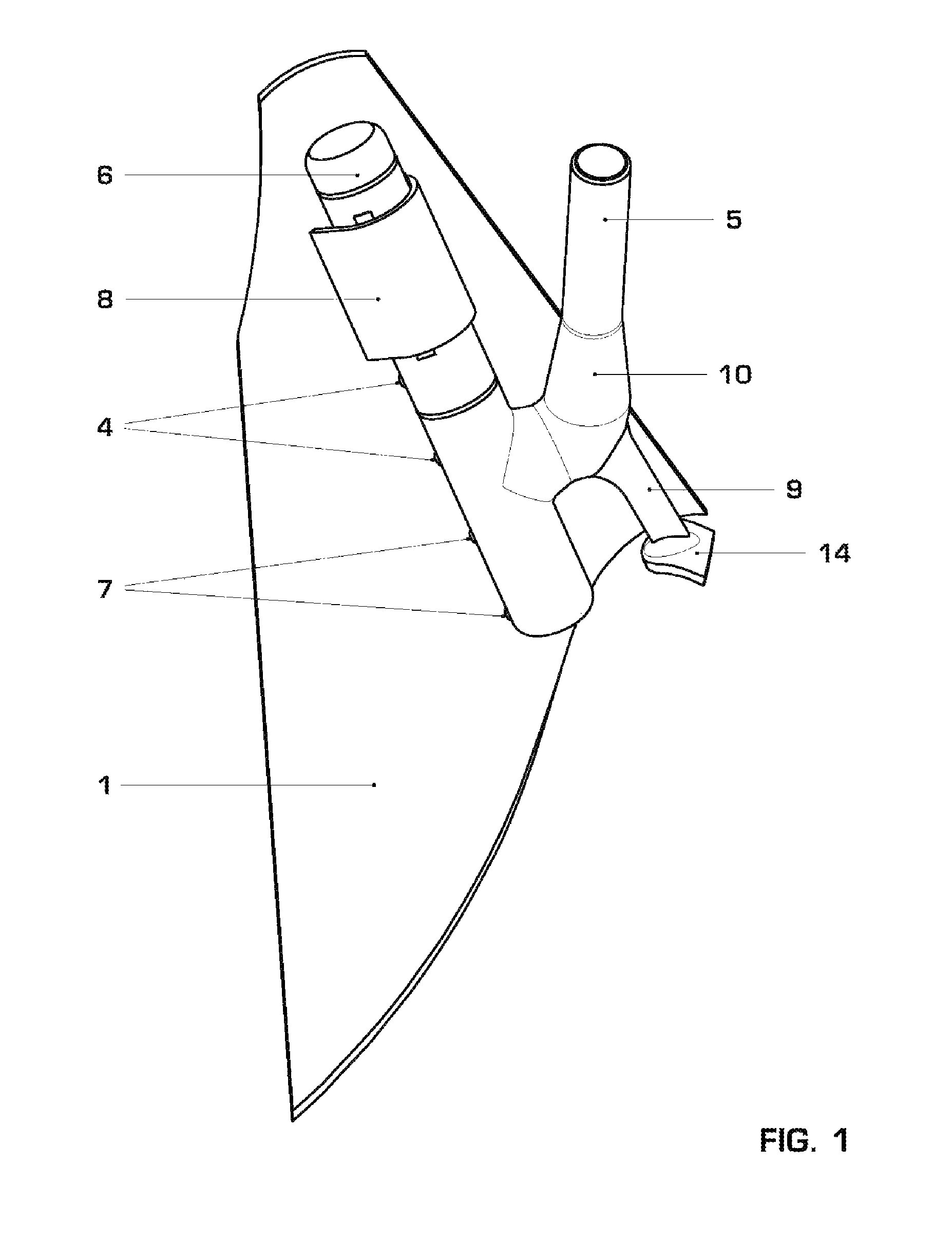
[0025]FIG. 1 is a three-dimensional illustration of a single burner shell 1, of which the top side facing away from the swirl space faces the observer so as to be visible.

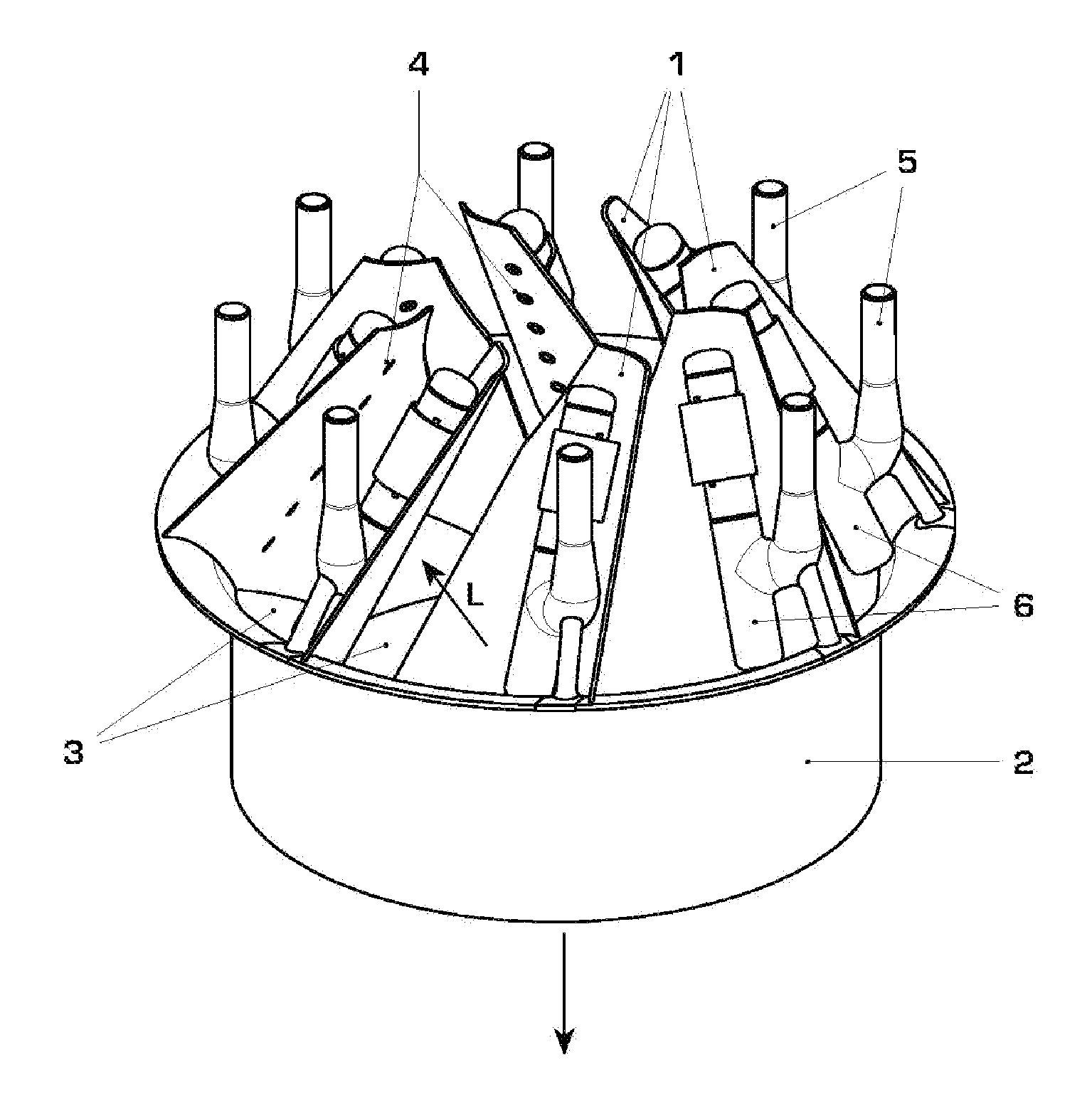
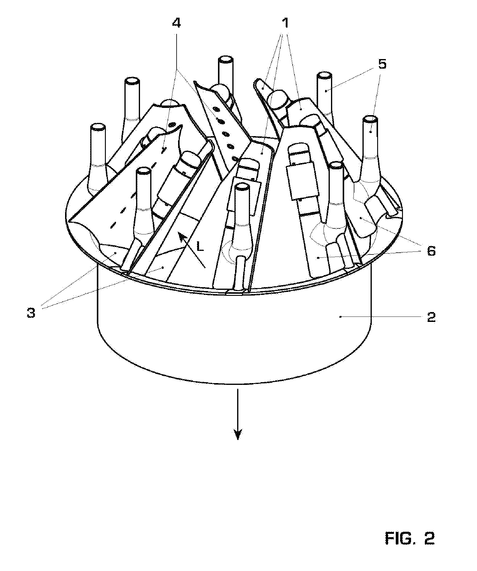
[0026]To make it easy to understand the spatial arrangement and type of functioning of the burner shell illustrated in FIG. 1, reference may made, furthermore, to the swirl generator, shown in FIG. 2, of a premixing burner which provides eight individual burner shells 1 which are arranged in the form of a crown around a molded element 2 and internally enclose with respect to one another in each case a conically widening swirl space. For the sake of greater clarity, a holding ring which is to be provided for the stability of the burner shells 1 and which centrally supports the upper ends of the burner shells in the illustration is not illustrated, especially since this is not of any further importance for explaining the subject matter of this application.

[0027]For the technical understanding of the burner shell arra...


PUM


Abstract

A premixing burner has a swirl generator with at least two burner shells (1) which jointly enclose an axia conically widening swirl space and delimit tangential air inlet slits (3) through which combustion supply air passes into the swirl space in which an axially propagating swirl flow is formed, and with fuel injection devices at least partially along the tangentially running air inlet slits (3). The fuel injection devices include a fuel line (6) separate from the burner shell (1) and which is firmly attached to the burner shell (1) so as to be longitudinally movable with respect to the burner shell (1) and releasable perpendicularly to the surface of the burner shell (1). In the burner shell (1), orifices (4) are provided, into which issue fuel injectors (7) which are provided along the fuel line (6) and which project beyond the circumferential edge of the fuel line (6).

Description

[0001]This application is a Continuation of, and claims priority under 35 U.S.C. §120 to, International application number PCT / EP2006 / 060355, filed 1 Mar. 2006, and claims priority under 35 U.S.C. §119 therethrough to Swiss application number 00407 / 05, filed 9, Mar. 2005, the entireties of which are incorporated by reference herein.BACKGROUND OF THE INVENTION[0002]1. Field of the Invention[0003]The invention relates to a premixing burner for generating an ignitable fuel / air mixture, with a swirl generator which provides at least two burner shells which complement one another to form a throughflow body and which jointly enclose an axially conically widening swirl space and delimit with respect to one another, in the axial longitudinal extent of the cone, tangential air inlet slits, through which combustion supply air passes into the swirl space in which an axially propagating swirl flow is formed, and with means for the injection of fuel, with are provided at least partially along th...

Claims


Application Information

Patent Timeline
Patent Type & Authority Patents(United States)
IPC IPC(8): F23M3/00
CPCF23C7/002F23D17/002F23R3/286F23C2900/07002F23D2211/00
Inventor RUCK, THOMASSLOWIK, SLAWOMIRSTEINBACH, CHRISTIANVON PLANTA, MARTIN ANDREA
Owner ANSALDO ENERGIA SWITZERLAND AG
Why Eureka
Try Eureka