
Bicomponent fibers, products formed therefrom and methods of making the same

a technology of bicomponent fibers and fibers, applied in the direction of filament/thread forming, textiles and papermaking, vehicle safety arrangments, etc., can solve the problems of low stiffness of fibers, low recovery, and low stiffness of nonwoven fabrics

Inactive Publication Date: 2015-05-07
ESSENTRA POROUS TECH
View PDF3 Cites 14 Cited by
  • Summary
  • Abstract
  • Description
  • Claims
  • Application Information

AI Technical Summary

Benefits of technology

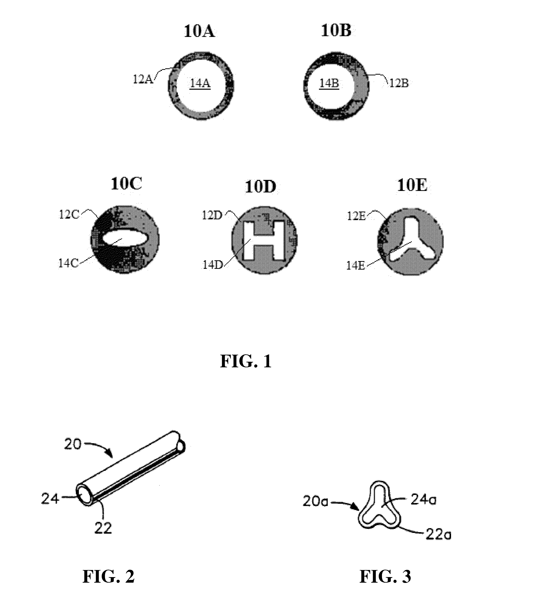
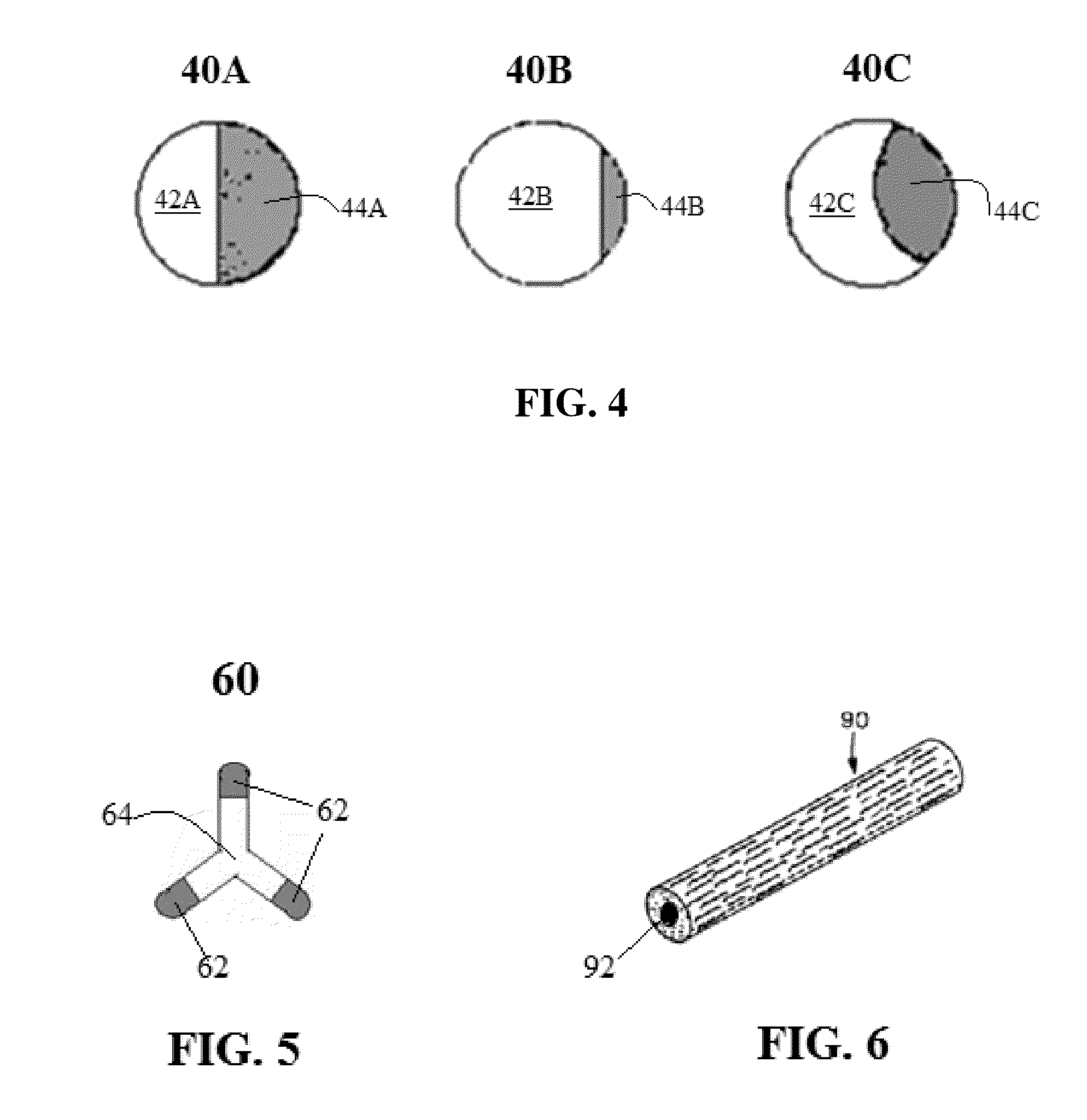
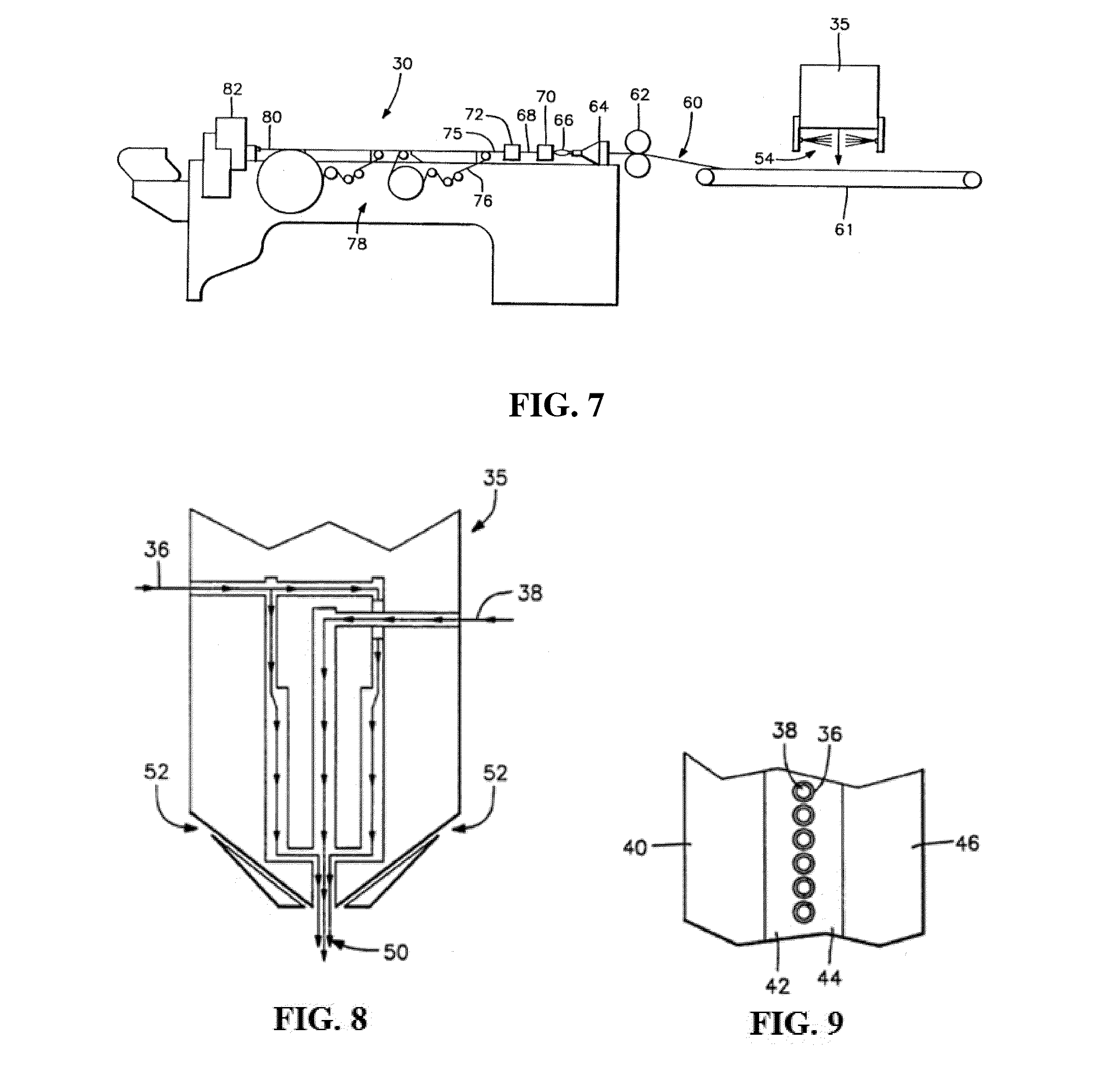
This patent describes a type of fiber made from two different thermoplastic polymers. The fibers have a sheath-core configuration, with the core made of one polymer and the sheath made of another polymer. The two polymers can have different melting points, and the fiber can be made by melt blowing. The fibers can be used to make nonwoven fabrics or rovings, which can be used for various applications such as ink reservoirs, air freshener, or medical diagnostic test devices. The nonwoven fabric can also be made from a combination of these bicomponent fibers and other fibers. The technical effect of this patent is the creation of a new type of fiber that has a unique structure and properties that make it useful in various applications.

Problems solved by technology

Nonwoven fabrics typically lack strength unless densified or reinforced by a backing or a structural frame.
Such structural reinforcements, however, may be undesirable since they may interfere with filter efficiency and may introduce impurities.
Such fibers, however, have low stiffness and very low recovery when compressed.
Moreover, they are not easily susceptible to thermal bonding and are difficult to bond by chemical means.
Thus, while they have been used in the production of thin, porous non-woven webs, they have not been commercially acceptable for the production of self-supporting, three-dimensional items such as ink reservoirs, wicks, or flat or corrugated filter sheets or direct formed filter tubes exhibiting high crush strength properties.

Method used


Image

  • Bicomponent fibers, products formed therefrom and methods of making the same
  • Bicomponent fibers, products formed therefrom and methods of making the same
  • Bicomponent fibers, products formed therefrom and methods of making the same

Examples


example

[0076]Melt blown filter tubes made of monocomponent nylon 6 (polycaprolactam) fiber (“Monocomponent Fiber Matrix”) and of sheath-core bicomponent fibers (sheath: poly(m-xylene adipamide and core: nylon 6) (“Bicomponent Fiber Matrix”) were tested to compare the extent to which the fiber matrices withstood pressure through the wall thickness of the filters. Both filter tubes had the same fiber size and density. Measurements of max load (lbf) and stiffness (lbf / in) were obtained (Table 1) from an Instron physical testing machine.

[0077]To test the strength of the fiber matrices, three (3) rectangular prism samples were cut from three (3) random positions on each filter. The top of the rectangular prisms represented the outside diameter of the filter and the bottom represented the inside diameter. Each sample was tested on the Instron machine, which applied vertical force to the top surface of the rectangular prisms, or the outside of the filter, which is the same direction of fluid flow...


PUM

PropertyMeasurementUnit
average diameteraaaaaaaaaa

Abstract

Melt blown bicomponent fibers comprising a first thermoplastic polymeric material and a second thermoplastic polymeric material comprising homo- or co-polymer(s) of poly(m-xylene adipamide) or polyphenylene sulfide. The first thermoplastic polymeric material may be one or more homo- or co-polymer(s) of nylon 6 (polycaprolactam), nylon 6,6 (poly(hexamethylene adipamide)), polypropylene, and / or polybutylene terephthalate. A plurality of bicomponent fibers may thermally bonded to one another at spaced apart points of contact to define a porous structure that substantially resists crushing. The nonwoven fabric webs and rovings and self-supporting, three-dimensional porous elements may be formed from the plurality of bicomponent fibers.

Description

CROSS-REFERENCE TO RELATED APPLICATIONS[0001]This application claims the benefit under 35 U.S.C. §119(e) of U.S. Provisional Application No. 61 / 901,108, filed Nov. 7, 2013, the entire contents of which are incorporated by reference as if fully set forth herein.FIELD OF THE INVENTION[0002]This invention relates to bicomponent fibers, to webs, rovings and self-supporting three-dimensional products formed therefrom, and to methods of making the same.BACKGROUND[0003]Bicomponent fibers are generally understood to refer to filaments which are produced by extruding two polymer systems from the same spinneret, with both polymer systems being contained within the same filament. Bicomponent fibers provide vast possibilities for creating fibers with various desired chemical and physical characteristics and geometric configurations, as different polymer systems can be used to exploit capabilities not existing in either polymer system alone. Moreover, bicomponent fibers may be produced using a m...

Claims


Application Information

Patent Timeline
Patent Type & Authority Applications(United States)
IPC IPC(8): D01F8/12B01D39/16D01F8/06D04H13/00A01N25/34D01F8/14
CPCD01F8/12A01N25/34B01D39/163D01F8/06D04H13/00D01F8/14D01D5/0985D01D5/32D01D5/34D04H1/56B01D2239/0233B01D2239/0622Y10T428/1362Y10T428/2929Y10T442/641D04H1/5412D04H1/5414D02G3/02D02G3/04D02G3/045D02G3/32D04H1/565
Inventor WARD, BENNETT C.DILLIE, BRENTON D.
Owner ESSENTRA POROUS TECH
Learn More