
Magnetic field shielding sheet for a wireless charger, method for manufacturing same, and receiving apparatus for a wireless charger using the sheet

a wireless charger and magnetic field shielding technology, which is applied in the direction of inductance, packaging, synthetic resin layered products, etc., can solve the problems of weak impact resistance, weak secondary batteries, and easy breakage of thinly processed ferrite sheets, so as to reduce loss, increase the quality factor of secondary coils, and excellent electric power transmission efficiency

Active Publication Date: 2015-05-07
AMOSENSE
View PDF4 Cites 130 Cited by
  • Summary
  • Abstract
  • Description
  • Claims
  • Application Information

AI Technical Summary

Benefits of technology

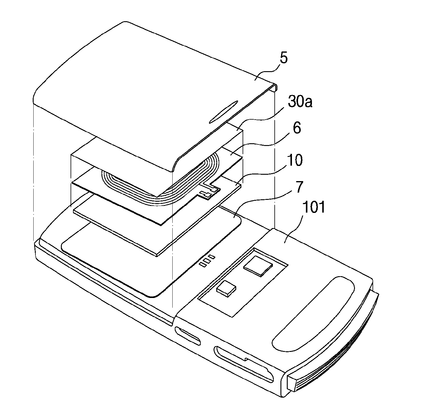
The present invention provides a magnetic field shield sheet for a wireless charger that reduces loss due to eddy currents by a flake treatment process of an amorphous ribbon. This shield sheet blocks a magnetic field from influencing upon the main body and battery of a portable mobile terminal device and improves the quality factor of a secondary coil. The invention also provides a method of manufacturing the shield sheet and a receiver for wireless charging using this shield sheet. Additionally, the invention fills a gap between fine pieces of an amorphous ribbon through the flake treatment process and prevents water penetration to promote reduction of eddy currents. The invention also establishes a shape of a shield sheet similar to that of a coil of a receiving device for wireless charging to exhibit high power transmission efficiency. The invention sequentially performs a flake treatment process and a laminating process to maintain sheet thickness and exhibit high productivity and inexpensive manufacturing costs.

Problems solved by technology

However, in association with miniaturization and weight reduction of electronic equipment, various electronic devices become light in the weight thereof, and accordingly a low contact pressure between electrodes of the power reception device and the power feeding device may cause problems such as charge failure charge error.
Further, secondary batteries are weak at heat, which needs to prevent the temperature rise of the batteries, and to pay attention to a circuit design so as not to cause overcharge and overdischarge.
However, in the case that a ferrite sheet is processed thinly, the thinly processed ferrite sheet may be easily broken and weak in impact resistance.
As a result, there have been problems that defects have occurred in the power reception device due to a fall or collision of the non-contact type charger.
Meanwhile, if a power transmission speed increases, defects between adjacent transformers, as well as defects caused by heat from the surrounding components, may be likely to occur.
As a result, large power cannot be transmitted and thus a time-consuming problem may be caused for charging the electronic device.
Therefore, it is difficult to respond to a thinning tendency of terminals.
However, when an alternating-current magnetic field according to frequency of 100 kHz used for power transmission is applied to the amorphous ribbon, functionality of applications may be reduced due to an influence of eddy currents of the ribbon surface, or problems of reducing wireless charging efficiency and causing heat generation may occur.
However, in the case that a processing treatment such as a flake treatment process of reducing a surface area of the ribbon is performed in order to further reduce the eddy current effects, the magnetic permeability is significantly degraded and the function as the shield sheet is greatly degraded.
A magnetization or saturation phenomenon occurs in a thin shield sheet due to a direct-current magnetic field of the permanent magnets, to thereby decrease the performance of the chargers or sharply decreasing the power transmission efficiency.
Conventional magnetic field shield sheets for wireless chargers do not present solutions for attaining the thin film but solving the heat generation problem due to shields and improving the wireless charging efficiency.

Method used


Image

  • Magnetic field shielding sheet for a wireless charger, method for manufacturing same, and receiving apparatus for a wireless charger using the sheet
  • Magnetic field shielding sheet for a wireless charger, method for manufacturing same, and receiving apparatus for a wireless charger using the sheet
  • Magnetic field shielding sheet for a wireless charger, method for manufacturing same, and receiving apparatus for a wireless charger using the sheet

Examples


example 9

[0197]An amorphous alloy ribbon sheet applied for a shield sheet was prepared by comprising: making an amorphous ribbon made of a Fe67B14Si1Co18 alloy in a thickness of 25 μm by a rapid solidification method (RSP) due to melt spinning; cutting the amorphous ribbon in a sheet form and heat treating the cut sheet at 487° C., 459° C., and 450° C., under no magnetic field, for 1 hour, respectively, to thereby obtain the amorphous ribbon sheet; inserting the amorphous ribbon sheet between a protective film of 10 μm thick using a polyethylene terephthalate (PET) base member and a double-sided tape (with a release film excluded) of 10 μm thick using a PET base member, to thereby prepare a laminate sheet; and performing flake treatment and lamination treatment processes respectively by using a flake treatment processing device of FIG. 8 and a laminating device of FIG. 11.

[0198]Here, one to nine nanocrystalline ribbon sheets to be used in a laminate sheet were laminated for heat treatment te...

example 10

[0201]The maximum charging efficiency of the laminated sheets for the number of laminated sheets was measured by using the amorphous ribbon sheet of the inductance (permeability) of 15 μH, and the results were shown in Table 5.

[0202]The maximum charging efficiency was obtained in the state where value of a time constant of the reception device was adjusted to make the efficiency set to a maximum value based on value of the inductance of the reception device of the wireless charger, that is, the secondary coil.

TABLE 5Maximum charging efficiency (%)Permeability1 sheet2 sheets3 sheets4 sheets15 μH61.368.771.171.9

[0203]Referring to Table 5, the efficiency was increased according to the number of laminated amorphous ribbon sheets, and the maximum charging efficiency was 71.9% in the highest in the case of four sheets.

[0204]As described above, the present invention greatly reduces a loss due to eddy currents by a flake treatment process of an amorphous ribbon, to thereby block an effect o...


PUM

PropertyMeasurementUnit
temperatureaaaaaaaaaa
sizeaaaaaaaaaa

Abstract

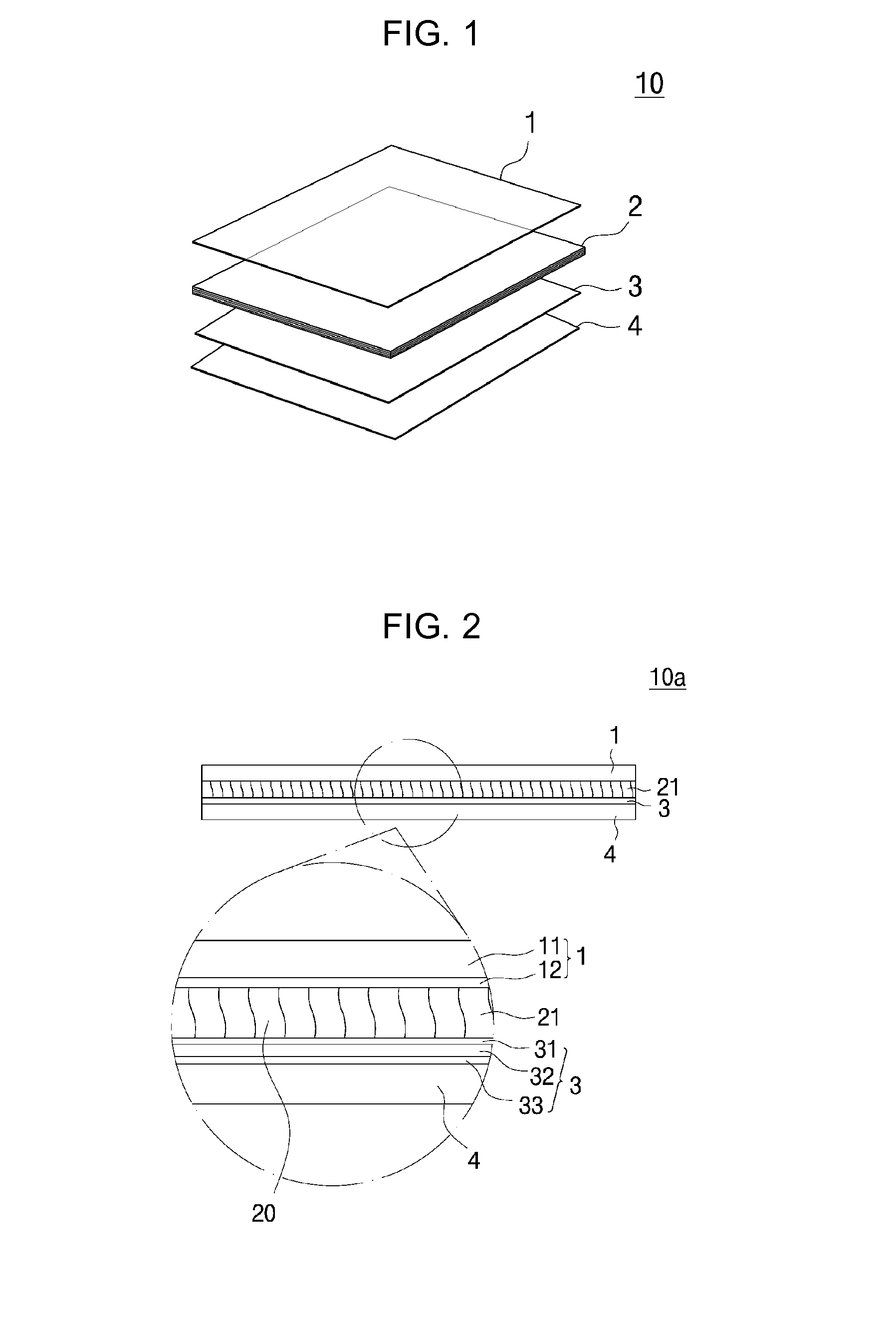
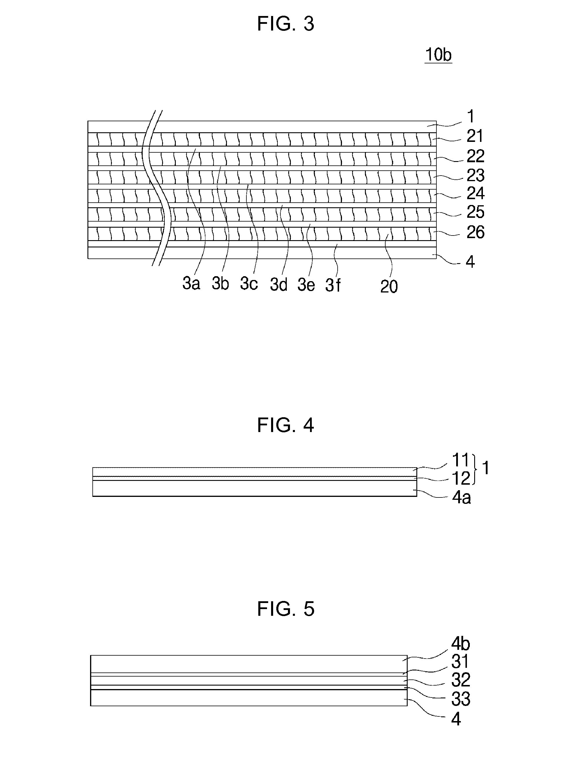
Provided are a magnetic field shield sheet for a wireless charger, which blocks an effect of an alternating-current magnetic field generated when a charger function for a portable mobile terminal device is implemented in a non-contact wireless manner on a main body of the portable mobile terminal device and exhibits excellent electric power transmission efficiency, a method of manufacturing the sheet, and a receiver for the wireless charger by using the sheet. The sheet includes: at least one layer thin magnetic sheet made of an amorphous ribbon separated into a plurality of fine pieces; a protective film that is adhered on one surface of the thin magnetic sheet via a first adhesive layer provided on one side of the protective film; and a double-sided tape that is adhered on the other surface of the thin magnetic sheet via a second adhesive layer provided on one side of the double-sided adhesive tape, wherein gaps among the plurality of fine pieces are filled by some parts of the first and second adhesive layers, to thereby isolate the plurality of fine pieces.

Description

TECHNICAL FIELD[0001]The present invention relates to a magnetic field shield sheet for a wireless charger, a method of manufacturing the magnetic field shield sheet, and a receiver for the wireless charger by using the magnetic field shield sheet, and more particularly to, a magnetic field shield sheet for a wireless charger, which blocks an effect of an alternating-current magnetic field generated when a charger function for a portable mobile terminal device is implemented in a non-contact wireless manner on a main body of the portable mobile terminal device and exhibits excellent electric power transmission efficiency, a method of manufacturing the magnetic field shield sheet, and a receiver for the wireless charger by using the magnetic field shield sheet.BACKGROUND ART[0002]As methods of charging secondary batteries mounted in electronic equipment such as portable terminals and video cameras, there are two types of charging methods, i.e., a contact type charging method and a no...

Claims


Application Information

Patent Timeline
Patent Type & Authority Applications(United States)
IPC IPC(8): H02J7/00B32B37/18B32B37/12H02J7/02B32B38/00
CPCH02J7/0042H02J7/025B32B37/18B32B37/12B32B38/0004H01F38/14Y10T428/25Y10T428/2848Y10T156/10Y10T428/249955Y10T428/249956H01F27/36H02J50/12H02J50/70H01F27/366H04B5/79B32B27/08H02J50/10H02J7/00Y10T428/32H05K9/0075H05K9/0081H05K9/0088H01Q7/08H01Q7/06
Inventor LEE, DONG HOONJANG, KIL JAE
Owner AMOSENSE
Learn More