
Light source apparatus and endoscope system

a light source and endoscope technology, applied in the field of light source apparatus and endoscope system, can solve the problems of inaccurate endoscopic imaging, spectrum change in an unwanted manner, and inability to stably obtain the emission spectrum of illumination light as a target of vessel enhancement imaging, etc., and achieve the effect of stably obtained

Inactive Publication Date: 2015-04-09
FUJIFILM CORP
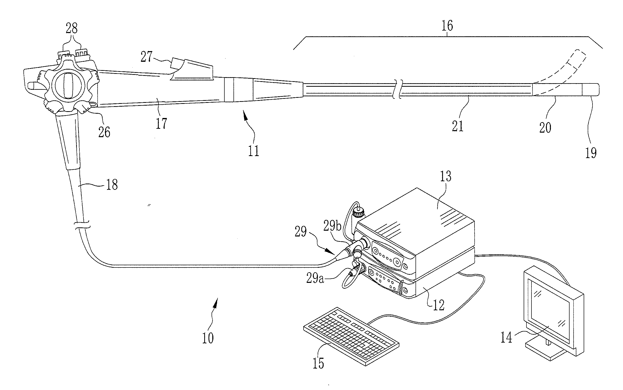
View PDF7 Cites 42 Cited by
  • Summary
  • Abstract
  • Description
  • Claims
  • Application Information

AI Technical Summary

Benefits of technology

The present invention is about using a fluorescent type of green semiconductor light source in a light source apparatus and endoscope system. The invention aims to provide stable illumination light of the target for endoscopic imaging. The invention has solved the problem of unwanted blue excitation light by using a wavelength cut-off filter component that cuts off part of the blue excitation light. This results in stable illumination light for endoscopic imaging.

Problems solved by technology

However, the combined construction of the light source apparatus has a drawback in that illumination light of an emission spectrum cannot be stably obtained as a target of the vessel enhancement imaging.
Assuming that color balance of a display image is changed typically in the vessel enhancement imaging by a change in the emission spectrum of the illumination light, a serious problem arises in incorrectness in the endoscopic imaging.
Thus, the spectrum will be changed in an unwanted manner.
For those reasons, it is impossible stably to produce illumination light of the spectrum of the target in the use of the fluorescent type of green semiconductor light source.
There is no known solution of this problem.
However, control of lighting for this conception will be very complicated and cannot be utilized practically.
No solution of this problem is known in the field of the endoscopic imaging.

Method used


Image

  • Light source apparatus and endoscope system
  • Light source apparatus and endoscope system
  • Light source apparatus and endoscope system

Examples


second preferred embodiment

[0133]In the first embodiment, the second dichroic mirror 80 includes the dichroic filter functioning as an excitation light cut-off filter. In the second embodiment, a dichroic mirror separate from the second dichroic mirror 80 has a dichroic filter functioning as an excitation light cut-off filter (wavelength cut-off filter component).

[0134]In FIG. 21, a path coupler 90 in a light source apparatus 85 includes a first dichroic mirror 91, which corresponds to the first dichroic mirror 79 of the first embodiment, and couples a light path of mixed light of the blue excitation light LBe and green fluorescence LGf from the green light source 36 with a light path of the red light LR from the red light source 37. A dichroic filter in the first dichroic mirror 91 operates also as an excitation light cut-off filter. In the path coupler 90, the path coupler 41 is repeated except for having the first dichroic mirror 91 instead of the first dichroic mirror 79.

[0135]As illustrated in FIG. 22, t...

third preferred embodiment

[0136]In FIG. 23, another preferred light source apparatus 95 is illustrated. A path coupler 96 has a dichroic mirror and an excitation light cut-off filter separate from the dichroic mirror. A wavelength cut-off filter 97 or excitation light cut-off filter (or reduction filter) is disposed between the green light source 36 and the first dichroic mirror 79. In FIG. 24, the wavelength cut-off filter 97 reflects light of a violet to blue wavelength range less than approximately 460 nm, and passes light of a green to red wavelength range other than the same. Furthermore, the wavelength cut-off filter 97 may be disposed between the first and second dichroic mirrors 79 and 80. In conclusion, entry of the blue excitation light LBe to the entrance end 55a of the light guide device 55 should be prevented. An excitation light cut-off filter can be disposed between the blue excitation light source device 44 and the light guide device 55, and more precisely, a coupling position (intersection p...

fourth preferred embodiment

[0137]In the first embodiment, the current values for the LEDs 43-45 are controlled. However, a light amount of a semiconductor light source relative to a current value of driving may be changed by influence of various factors, including heat generated by LEDs or phosphor or degradation with time. In the fourth embodiment, measurement sensors are used for measuring light amounts of the colors, to monitor a reach of the light amounts of the colors to a target value according to an output signal from the measurement sensors.

[0138]In FIG. 25, a path coupler 100 in a light source apparatus 99 has the elements in the path coupler 41 of FIG. 18, and also includes a blue measurement sensor 101, a green measurement sensor 102 and a red measurement sensor 103 for light amounts, and glass plates 105, 106 and 107. The measurement sensors 101-103 measure the light amounts of the light of the colors from the B, G and R light sources 35-37. The glass plates 105-107 are disposed directly downstrea...


PUM


Abstract

A fluorescent type of green light source of a semiconductor in a light source apparatus for an endoscope includes a blue excitation light source device and green emitting phosphor. The blue excitation light source device emits blue excitation light. The green emitting phosphor is excited by the blue excitation light, and emits green fluorescence. A dichroic filter in a dichroic mirror cuts off the blue excitation light from an emission spectrum of mixed light of the blue excitation light and green fluorescence from the fluorescent type of green light source. Thus, illumination light with the emission spectrum of a target can be stably supplied without influence of the blue excitation light to a light amount of blue light from a blue light source of a semiconductor.

Description

CROSS-REFERENCE TO RELATED APPLICATION[0001]This application claims priority under 35 USC 119 from Japanese Patent Application No. 2013-208215, filed 3 Oct. 2013, the disclosure of which is incorporated by reference herein.BACKGROUND OF THE INVENTION[0002]1. Field of the Invention[0003]The present invention relates to a light source apparatus and endoscope system in which a fluorescent type of green semiconductor light source is used, and illumination light of an emission spectrum of a target for use in endoscopic imaging can be stably obtained.[0004]2. Description Related to the Prior Art[0005]Endoscopic imaging with an endoscope system is widely known in the field of medical diagnosis. The endoscope system includes an endoscope, a light source apparatus and a processing apparatus. The light source apparatus supplies light to the endoscope. The processing apparatus processes an image signal output by the endoscope. The endoscope includes an elongated tube for entry in a body cavity...

Claims


Application Information

Patent Timeline
IPC IPC(8): H01L33/50A61B1/06H05B33/08F21V8/00H01L27/15H01L33/58H05B44/00
CPCH01L33/50H01L27/15H01L33/58A61B1/0638G02B6/0005A61B1/0661H05B33/0854A61B1/00057A61B1/0646A61B1/0653A61B1/0684A61B1/07A61B1/043G02B23/2469G03B2215/0567H01L2924/181H01L2224/48091H01L2224/49107H05B45/12A61B1/0655H01L2924/00012H01L2924/00014
Inventor MORIMOTO, YOSHINORIOZAWA, SATOSHIOHASHI, EIJI
Owner FUJIFILM CORP
Learn More