
Method for synthesising trifluoroethylene from chlorotrifluoroethylene

Active Publication Date: 2015-04-02
ARKEMA FRANCE SA
View PDF10 Cites 1 Cited by
  • Summary
  • Abstract
  • Description
  • Claims
  • Application Information

AI Technical Summary

Benefits of technology

The patent describes a process for making a chemical called VF3, which is highly effective in converting certain compounds to other useful ones. The process has a high conversion rate of up to 80% and is very selective for the desired product. The process is also designed to reduce the risk of explosions and lower the reaction temperature, making it suitable for industrial use.

Problems solved by technology

The main risks related to the use of this product relate to its flammability, its propensity to self-polymerization when it is not stabilized, its explosiveness due to its chemical instability and its supposed sensitivity to peroxidation, by analogy with other halogenated olefins.
However, the major danger is associated with the propensity of VF3 to violently and explosively decompose under certain pressure conditions in the presence of an energy source, even in the absence of oxygen.
The risk of peroxidation and also the risk of self-polymerization increase in the presence of a liquid phase.
There is a risk of explosion as a result of a peroxidation or of an initiation of polymerization during the storage of this type of molecule.
In view of the main risks above, the synthesis and the storage of VF3 present specific problems and impose strict safety rules throughout these processes.
The lifetime of these catalysts is relatively short and it is difficult to obtain good selectivity for VF3 if the conversion of the CFC-113 is increased.
However, the operating conditions are difficult and the degree of conversion of the HFC-134a is low, just like the trifluoroethylene yield.
The reaction conditions are mild, but the starting materials are difficult to find and the reaction produces a great deal of effluents.
This technique for the manufacture of trifluoroethylene exhibits a relatively high yield; however, the reaction temperature is high (between 325-425° C.) and the catalyst easily loses its activity.
It also exhibits difficulties in collecting, separating and purifying the reaction products.
On comparing the technique for the production of trifluoroethylene from CTFE with that which starts from CFC-113, there is a decrease in the reaction products, with a relatively large increase in the trifluoroethylene yield; however, problems of lifetime of the catalyst and the difficulties in collecting, separating and purifying mentioned for the other routes also exist with this technique.

Method used


Image

  • Method for synthesising trifluoroethylene from chlorotrifluoroethylene
  • Method for synthesising trifluoroethylene from chlorotrifluoroethylene

Examples


example 1

Test of the Performances of the Catalysts

Preparation of the Catalytic Charge

[0050]The bed of catalyst to be tested is inserted between two layers of inert substances, such as corindon or silica. In order, a first layer of corindon is introduced, over a height of 50 cm, into a tubular reactor consisting of a stainless steel tube with a length of 1200 mm over a diameter of 25 mm equipped with a jacket. A layer representing 100 cm3 of test catalyst is subsequently introduced onto this layer and then corindon is again introduced above the layer of catalyst until the reaction tube is completely filled.

[0051]The catalyst thus charged is subsequently activated under a stream of hydrogen in the following way: the reaction tube is placed in a tubular furnace and is fed via the top with a stream of hydrogen of 2 mol / h. The furnace is then heated up to 400° C. and the system is left under the same stream of hydrogen for 12 h. After this period of activation at 400° C. (chemical reduction of th...

example 2

Implementation of the Process According to the Invention

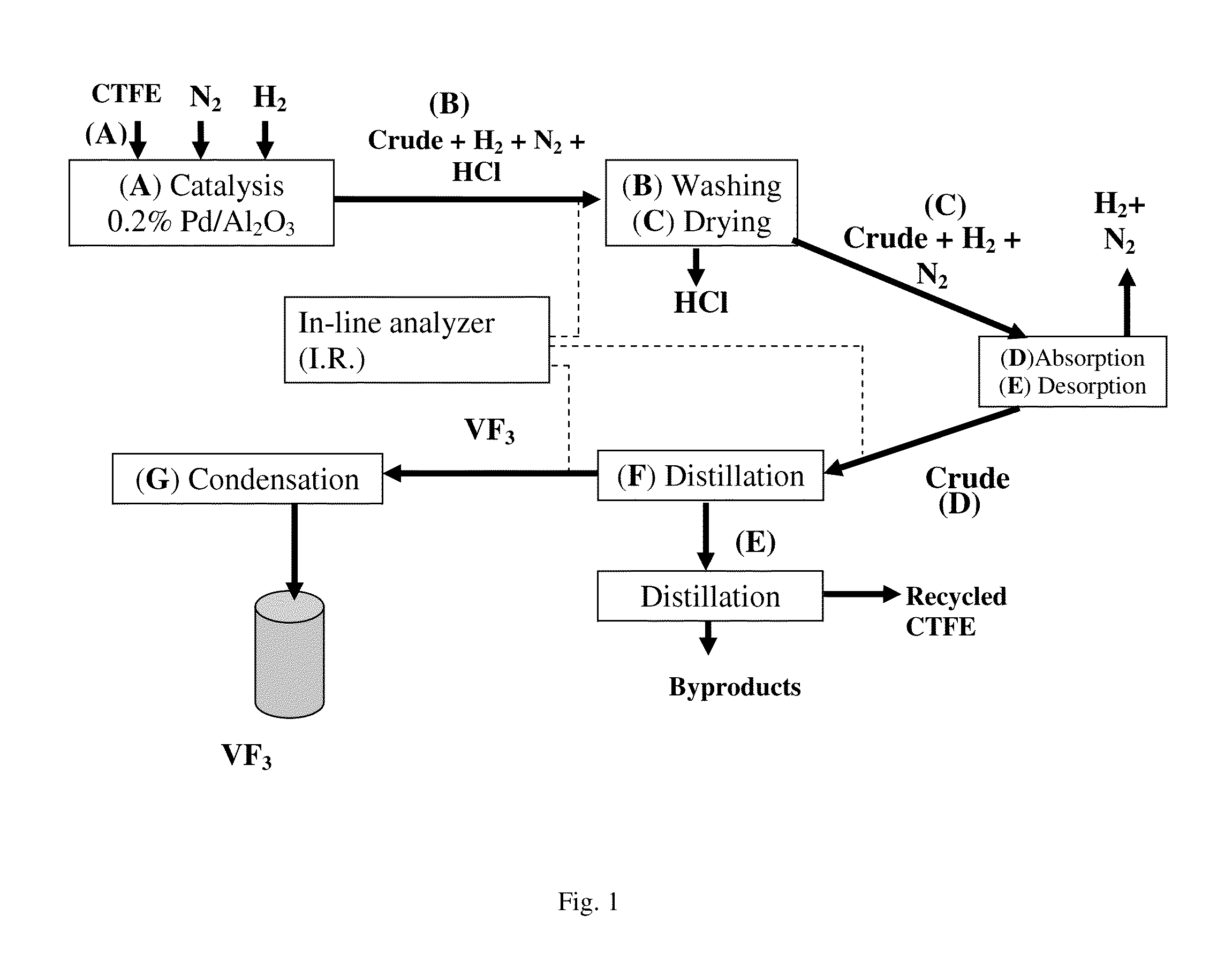
[0060]The micropilot plant represented diagrammatically in FIG. 1 was operated in the following way:[0061]4 hydrogenolysis reactors (A), each composed of a metal tube made of stainless steel with a length of 1200 mm and with a diameter of 25 mm, equipped with a jacket over the entire length of the tube, are charged with the following mixture:[0062]66 ml (110 g) of corindon;[0063]275 ml (436 g) of 0.2% Pd / Al2O3 catalyst (BET specific surface=5.3 m2 / g and a pore volume 3 / g);[0064]45 ml (78 g) of corindon.[0065]the catalytic composition is reduced at 250° C. for 6 hours by a flow rate of 1 mol / h of hydrogen.[0066]the jacket of each reactor is subsequently fed with a heat-exchange fluid thermostatically controlled at 25° C.[0067]each reactor is fed with 1 mol / h of CTFE and 1 mol / h of hydrogen. It is also possible to feed the reactors with an inert gas (in this case nitrogen).

[0068]The contact time, calculated as being the ratio of ...

example 3

Preparation of a VF2 / VF3 Copolymer

[0082]396 g of VF3 and 750 g of VF2 are charged to a reactor containing 1862 g of demineralized water, 0.34 g of methylhydroxypropylcellulose and 1.8 g of dipropyl peroxydicarbonate. The reactor is then brought to the temperature of 44° C. The reaction starts and is reflected by a fall in the pressure of the reactor which is compensated for by continuous injection of water. When 700 g of water have been introduced, the injection of water is halted and the pressure falls down to 65 bar. The reactor is then heated to 65° C. and the pressure continues to fall. When the pressure reaches 38 bar, the reactor is cooled down and is then emptied. The reaction mixture collected is filtered and the cake obtained is washed 5 times in 3 l of clean water before being dried in an oven at 70° C. to constant weight. The composition of the resin, analyzed by 1H NMR, is found to be equal to 31.2 mol % of VF3. The thermal characterization by DSC reveals a ferroelectric...


PUM

PropertyMeasurementUnit
Temperatureaaaaaaaaaa

Abstract

The present invention relates to the preparation of trifluoroethylene (VF3 or TrFE) by hydrogenolysis of chlorotrifluoroethylene (CTFE) in the gaseous phase over a group VIII metal catalyst deposited on a support. This method can be used to obtain VF3 in an economical manner in conditions which minimize the risk of explosion of this molecule. Using a catalyst containing a group VIII metal and, more specifically, containing Pd deposited on a support and a specific series of steps of separation and purification makes it possible to obtain excellent CTFE conversion rates and high selectivity in VF3 at atmospheric pressure and at low temperatures.

Description

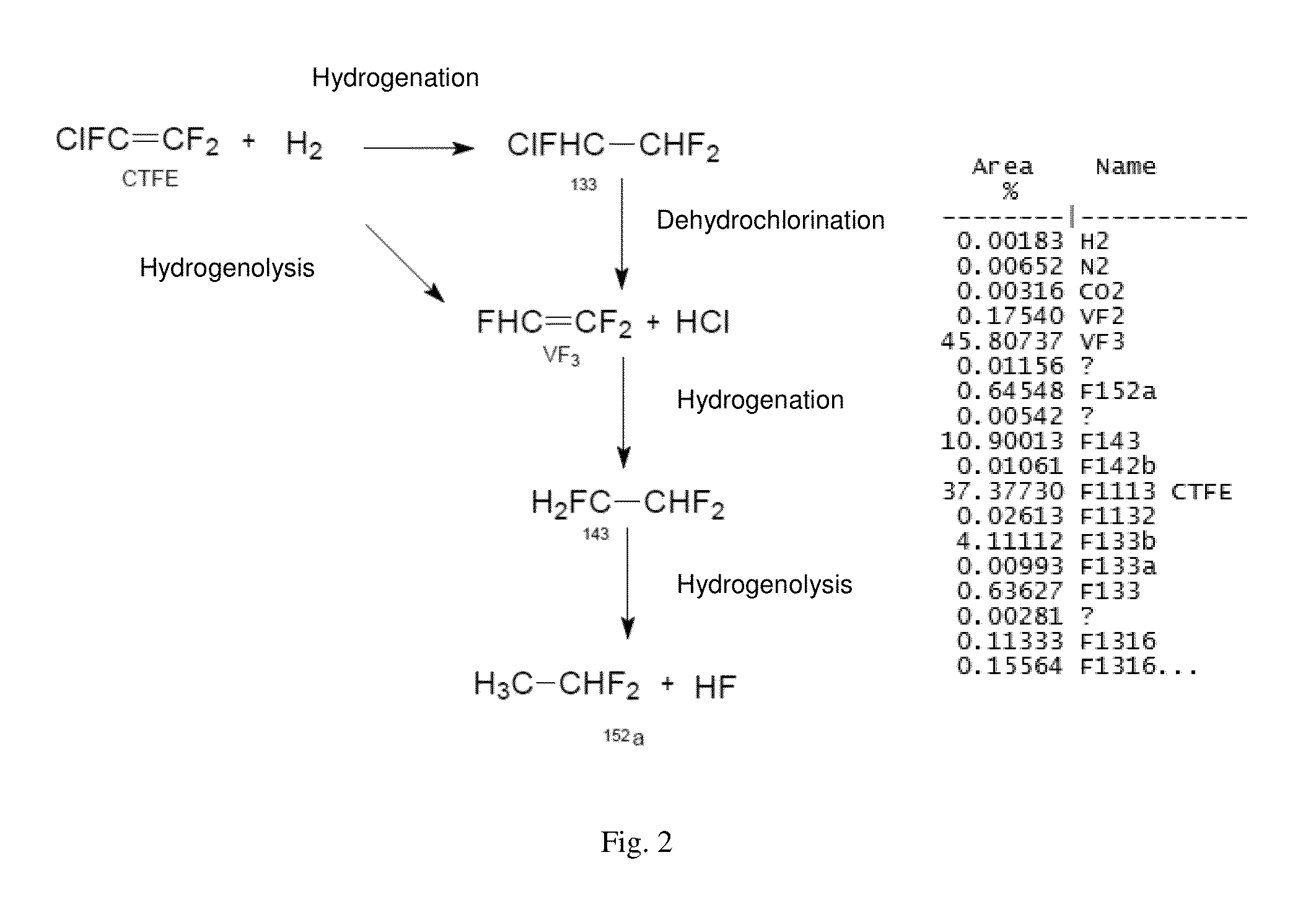
FIELD OF THE INVENTION[0001]The present invention relates to the field of unsaturated fluorohydrocarbons and has more particularly a subject matter of the preparation of trifluoroethylene (VF3 or TrFE) by hydrogenolysis of chlorotrifluoroethylene in the gas phase over a catalyst of a metal from Group VIII deposited on a support.TECHNICAL BACKGROUND[0002]Fluoro-olefins, such as VF3, are known and are used as monomers or comonomers in the manufacture of fluorocarbon polymers exhibiting noteworthy characteristics, in particular an excellent chemical strength and a good thermal resistance.[0003]Trifluoroethylene is a gas under standard pressure and temperature conditions. The main risks related to the use of this product relate to its flammability, its propensity to self-polymerization when it is not stabilized, its explosiveness due to its chemical instability and its supposed sensitivity to peroxidation, by analogy with other halogenated olefins. Trifluoroethylene exhibits the disting...

Claims


Application Information

Patent Timeline
IPC IPC(8): C07C17/23C08F214/22
CPCC08F214/22C07C17/23B01J23/44C07C17/383Y02P20/129H10N30/857H10N30/098B01J35/612B01J35/635C07C21/18
Inventor LEDUC, PHILIPPELANNUZEL, THIERRYGARRAIT, DOMINIQUEHUB, SERGEGUIRAUD, EMMANUELDOMINGUES DOS SANTOS, FABRICE
Owner ARKEMA FRANCE SA
Learn More